Reverse engineering techniques: From 3D scanning to the CAD file in the concrete industry
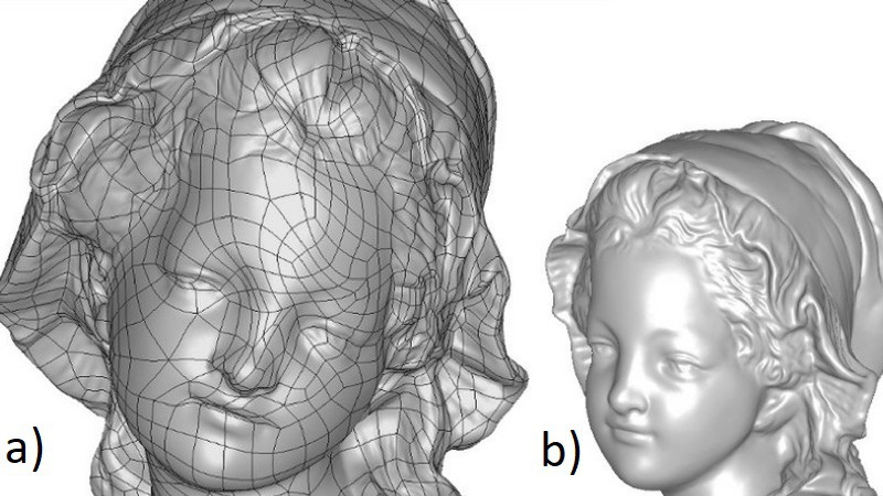 Figure 1a+b: University of Perugia
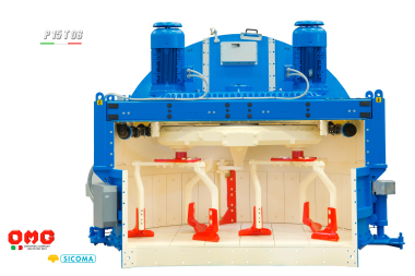
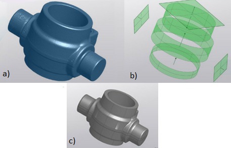 Figure 2a+b+c: University of Perugia
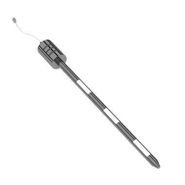
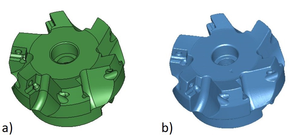 Figure 3a+b: University of Perugia


The use of a CAD model is essential in many activities, such as manufacturing, design and mechanics. This paper describes the various reverse engineering techniques and how this procedure, associated with 3D scanning, can be advantageously applied to the concrete industry for digital production and for empowering and optimizing production plants.
The use of a CAD model is essential in many activities, such as manufacturing, design and mechanics. Reverse engineering is the procedure for reconstructing the CAD model of an object or component from measurements gathered by surveys of the object itself. Naturally, the measurements on the components can be performed using different techniques and instruments, but, currently, the best and most effective technique for geometrical surveys of objects is 3D scanning by means of 3D optical non-contact scanners.
This paper describes the various reverse engineering techniques and how this procedure, associated with 3D scanning, can be advantageously applied to the concrete industry for digital production and for empowering and optimizing production plants.
1 Introduction
In industrial activities related to mechanics, manufacturing and design, projects of parts or assemblies are prepared and processed through CAD models, for the production or simulation of mechanical or structural behavior.
The CAD model is thus an indispensable tool for most industrial processes, such as machining, which can be carried out by means of CAD/CAM programs, by designing tool paths starting from the 3D geometries of the components to be produced.
In the concrete industry, CAD models are indispensable either for the design, production and optimization of machinery in production plants [1], [2], [3], [4] or for the numerical and digital simulation of the correct operation of concrete machinery and components [5], [6], [7], [8] and of the mechanical behavior of mixtures in contact with mixing blades or static structures [9], [10], [11], as well as for the development of digital production techniques for concrete products, such as cutting-edge 3D concrete printing techniques mainly used in the precast industry [12], [13], [14], [15]. At the current state of the art, concrete 3D printing is undoubtedly revolutionizing production and prototyping techniques, not least as a result of the technological advances that allowed the manufacture of the first 3D concrete printers able to realize works of art, architectural elements, but also entire buildings.
In addition to 3D printing, the launch and continuous technological advancement of 3D scanners opens up the opportunity of applying new design, control and manufacturing techniques based on the 3D digital reconstruction of concrete components or existing mechanical components.
In fact, a 3D scanner is an instrument allowing non-contact reconstructions of even complex geometries with very high accuracy [16], [17], [18]. Such reconstructions are generated in the form of polygonal 3D models, which can be used as a basis for the redesign or optimization of the components themselves or of the production cycles [19], [20], for dimensional and quality control using non-destructive techniques [21], [22], or for structural/mechanical simulation purposes.
Starting from the polygonal reconstruction carried out by a 3D scanner, a procedure termed reverse engineering makes it possible to reconstruct the CAD model of the component under examination whilst also providing the opportunity of reproducing the initial design intent and the specifications of the original project. Obviously, the measurements and acquisitions on the components can be accomplished with different tools, instruments and techniques and not only with 3D scanners, even if 3D scanning is currently the most effective technique for detecting the geometry of an object.
Reverse engineering is an indispensable procedure in many cases, such as when the original drawings of a component are no longer available and there is a need for recreating them, when a new component must be designed from an existing one, or when parts already in production must be updated by redesigning them in order to compensate for any defects that arose during production and to optimize the production process.
This paper will discuss various instruments, tools and techniques for the measurement and digital reconstruction of components and the different reverse engineering techniques to be applied in industrial sectors, as well as in the concrete industry for digital production and for the upgrading and optimization of production plants, as already highlighted.
2 Measurement and digital reconstruction of components: Instruments and methods
As already mentioned, the starting point for a reverse engineering procedure is the detection of the component under examination in order to partially or globally reconstruct its geometry in the form of 2D sketches, point detection or complete 3D reconstructions by means of polygonal 3D models, which are also called meshes.
Measurements on the components can be performed with different instruments and techniques, mainly depending on the geometric and dimensional characteristics of the parts and on the available measuring instruments.
The traditionally most known reconstruction method implies the use of simple measuring instruments such as calipers and meters. Indeed, this technique is very slow, and above all, it is not applicable to components with complex or freeform geometries. In fact, these instruments can be advantageously used just for parts having regular and known geometrical features, such as cylinders, spheres, cones, planes, etc. The use of this technique is also associated with a high degree of measurement uncertainty since the result is often too dependent on the operator or on the position of the instrument during the measurement, leading to results that are not always reliable.
Thus, the correctness of the result largely depends on the ability of the operator, who must not only be able to correctly handle the measuring instrument but also to evaluate the most suitable areas to be measured to obtain a reliable value, and to guess the intent of the original component designer.
Furthermore, the reconstruction of the component’s CAD model from these measurements is a completely manual procedure very similar to redesigning the component from the beginning. At the current state of technology, we can therefore consider this way of performing an effective reverse engineering procedure as obsolete.
Another technique for measuring parts implies the use of CMMs (coordinate measuring machines). These instruments allow the point-by-point detection of the object’s surfaces by means of contact probes.
The most important advantages in the use of CMMs are that they ensure a very high performance in terms of precision and accuracy of the measurement and, compared to other measurement methods, they allow detecting areas that are not commonly accessible for other measuring instruments, thanks to the option of mounting very small probing heads.
Their main disadvantages are the low continuous scanning speed, due to the point-by-point acquisition, and the ineffectiveness in detecting complex geometries. The measurement speed of a coordinate measuring machine is certainly higher than what can be achieved with manual techniques, such as the use of calipers and meters, but not comparable with the speed of an optical 3D scanner. In addition, contact-measuring machines are equipped with bulky structures or fixed articulated measuring arms, which make their use less flexible and more difficult than non-contact measuring instruments, which can even be portable and handheld, without fixing any reference point.
The currently most innovative and effective technique for measuring and generating complete 3D acquisition of components is 3D scanning using non-contact optical 3D scanners. Naturally, there are 3D scanners with different technical specifications and performance parameters. The better the quality of the 3D scanner used for the acquisition, the more reliable the obtained measurements and the resulting reverse engineering procedure will be.
2.1 3D scanners and optical non-contact digital reconstructions
At the current state of technology, there are different types of optical 3D scanners. An optical 3D scanner is an instrument allowing reconstructions of any real object, delivering results in terms of polygonal digital models (triangular meshes or point clouds) that represent the surface of the scanned object.
Some optical scanners allow complete and real-time reconstructions of any object thanks to automated mechanisms or due to their portability. The acquisition with portable and handheld instruments is particularly fast and easy because the instrument can also be used on components assembled and mounted in their operating environment. This is the case, for example, of mechanical parts used in concrete mixers, or of prefabricated concrete components already installed. Another example are statues or works of art, such as friezes and decorations of buildings, which cannot be dismantled for scanning purposes.
Being non-contact instruments, 3D optical scanners are even more suitable for application in the concrete industry since the components made of this material could undergo surface alterations if measured with contact probes.
The performance parameters of optical 3D scanners, in terms of achievable accuracy and precision, can be lower than those related to a contact coordinate measuring machine, but no instrument can match them from the point of view of effectiveness, efficiency, and speed. Thus, at the current state of the art, optical 3D scanning is the optimal solution for measuring components in order to recreate the CAD model through reverse engineering.
Optical 3D scanners work according to different optical detection principles, such as laser or structured light triangulation, confocal microscopy, interferometry and photogrammetry. Each principle has its own field of application and, in the case of the concrete industry, the most effective systems from a technical/economic point of view are laser or structured light triangulation systems, which reconstruct the object’s surfaces by projecting light patterns onto the scene and processing the data acquired by the cameras using triangulation algorithms.
They can be mounted on robotic measuring and control stations, and this can be particularly useful in situations where large objects need to be scanned in difficult-to-access locations.
3 Reverse engineering: Methods and techniques
As already mentioned, no 3D scanner, however expensive and performing, can automatically generate a CAD model as its output.
In fact, a 3D scanning system outputs 3D models in the form of polygons or point clouds in STL, OBJ, PLY, or other similar file formats.
For this reason, to generate a parametric or non-parametric CAD file starting from 3D scanning data, reverse engineering procedures must be implemented. There are various possible techniques, depending on the type of component to be reconstructed, the aim and final use of the resulting CAD model and the required quality of the result.
These techniques can be classified into three macro categories defined as follows:
1. Auto-surfacing
2. Extraction of CAD entities
3. Total reverse engineering
3.1 Auto-surfacing
The first technique to generate a CAD model starting from a mesh implies the use of software tools for automatic recognition of complex surfaces, such as NURBS (Non-Uniform Rational Basis Splines), which interpolate the triangular surfaces of the mesh. This operation is commonly called auto-surfacing and this technique is certainly very popular for various applications because it can be performed automatically or semi-automatically by the reverse engineering software.
The advantage of this method is that a complete CAD model can be obtained by launching a single command, after having performed simple mesh optimization operations.
However, the obtained result is not exactly the original CAD model of the component, but simply a model resulting from interpolation with many trimmed surfaces, which approximate the surface detected by the 3D scanner. Therefore, there is a sort of “peel” which envelopes the generated solid model.
This technique is effective only when the object geometry is freeform, such as for statues, friezes and moldings, while its use is strongly discouraged for mechanical components for which it is often necessary to obtain a CAD model on the basis of the original intent of the designer.
3.2 Extraction of CAD entities
Another reverse engineering technique involves the extraction of mathematical entities from the mesh in the form of regular surfaces such as cylinders, planes, cones, spheres, and even some NURBS surfaces for freeform parts. In this case, the mesh resulting from the scanner must be selected by regions and interpolated with the best-fit surfaces. These surfaces are normally reconstructed by the reverse engineering software, but to recreate a CAD model consistent with the original project conceived by the designer, it is necessary to evaluate if any deformations or wear in the scanned component have occurred, so as to compensate them in the reverse engineering phase. For this reason, auto-surfacing tools must be used extremely sparingly.
Different degrees of interpolation precision can be selected, and all the mathematical entities created by mesh interpolation can be subsequently exported to any CAD software, even devoid of reverse engineering tools, to be processed.
At this point, CAD modeling involves trimming the surfaces and making any changes using the common tools and commands available in 3D CAD software in order to obtain the complete CAD model.
This technique is more effective and reliable than the auto-surfacing technique because the CAD model can be reconstructed by carrying out a real redesign, retracing the initial design intent. Therefore, it is clear that the quality of the result depends on the experience and skill of the operator and furthermore this technique can be applied only to objects with simple geometries; this is the case of prefabricated concrete objects or components or simple mechanical parts used in concrete production machinery.
The result of this reverse engineering method can however be used for any purpose: from redesigning components to 3D printing of parts, even directly concrete-made 3D printed parts.
3.3 Total reverse engineering
The total reverse engineering technique is the most effective but involves the use of advanced tools and software for reverse engineering. In this case, the reverse engineering software must integrate both mesh editing tools and all the most advanced features (better if parametric) of a 3D CAD software. In fact, the quality of the result will increase in line with the performance of the used software and the number of tools made available by it.
Using this software, the mesh can be optimized and then we can work directly on it by creating curves, surfaces and solids that interpolate the result of the scan. Therefore, both surface and solid modeling can be performed. In doing so, we can work on the component just like the original designer would do because all the modeling tools are available.
Therefore, working with this reverse engineering technique requires particular skills and ability of the operator whose experience affects the quality of the result. The obtained high-quality result will be usable for any purpose, from simple applications such as 3D printing of concrete components to the redesign or optimization of complex components for concrete production machinery, such as mixing blades of concrete mixers. Moreover, this procedure makes it possible to reverse objects of any shape, even particularly complex parts, returning the result also in native formats of the most common CAD software suites.
4 Conclusions
The use of a 3D CAD model is increasingly essential in many activities in the concrete industry for digital production and for the upgrading and optimization of production plants. In particular, the various techniques for the reconstruction of a CAD model starting from optical 3D scanning data, through reverse engineering procedures, allow focusing the attention on the application of the various 3D scanning technologies instead of the most obsolete alternatives in the concrete industry. The use of these technologies and 3D data processing procedures constitute the near future in the field of concrete.