3D measurement systems: from the measuring point to the BIM model
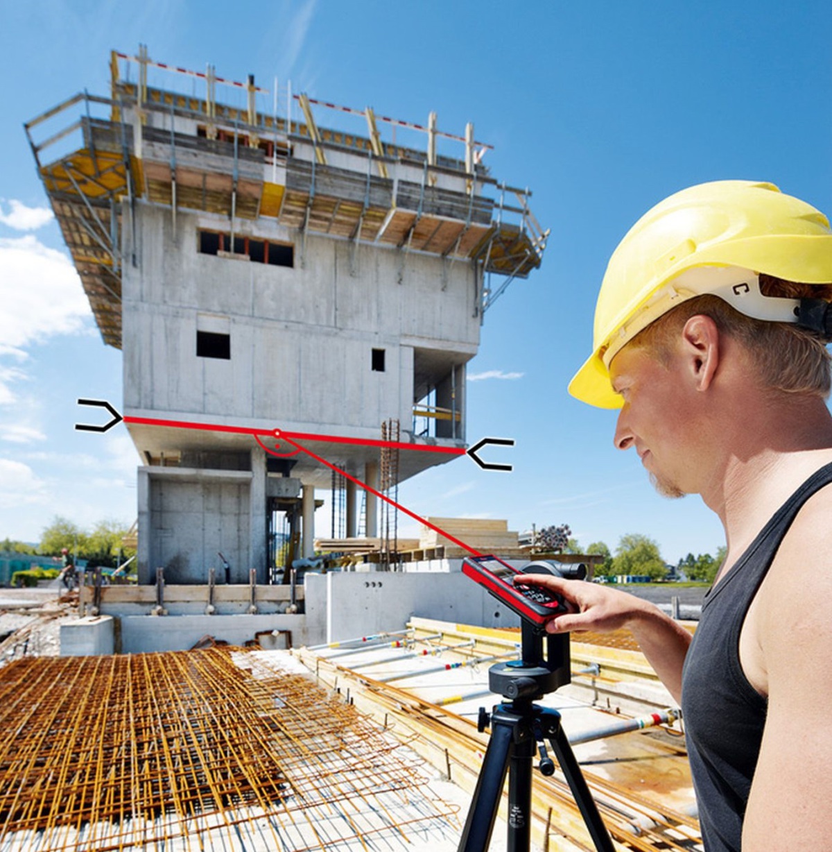 Figure: Leica Geosystems
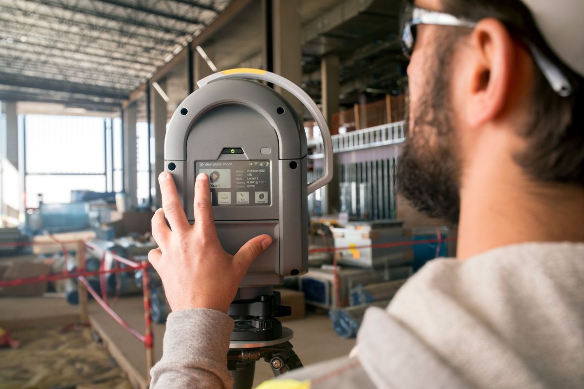 Figure: Trimble
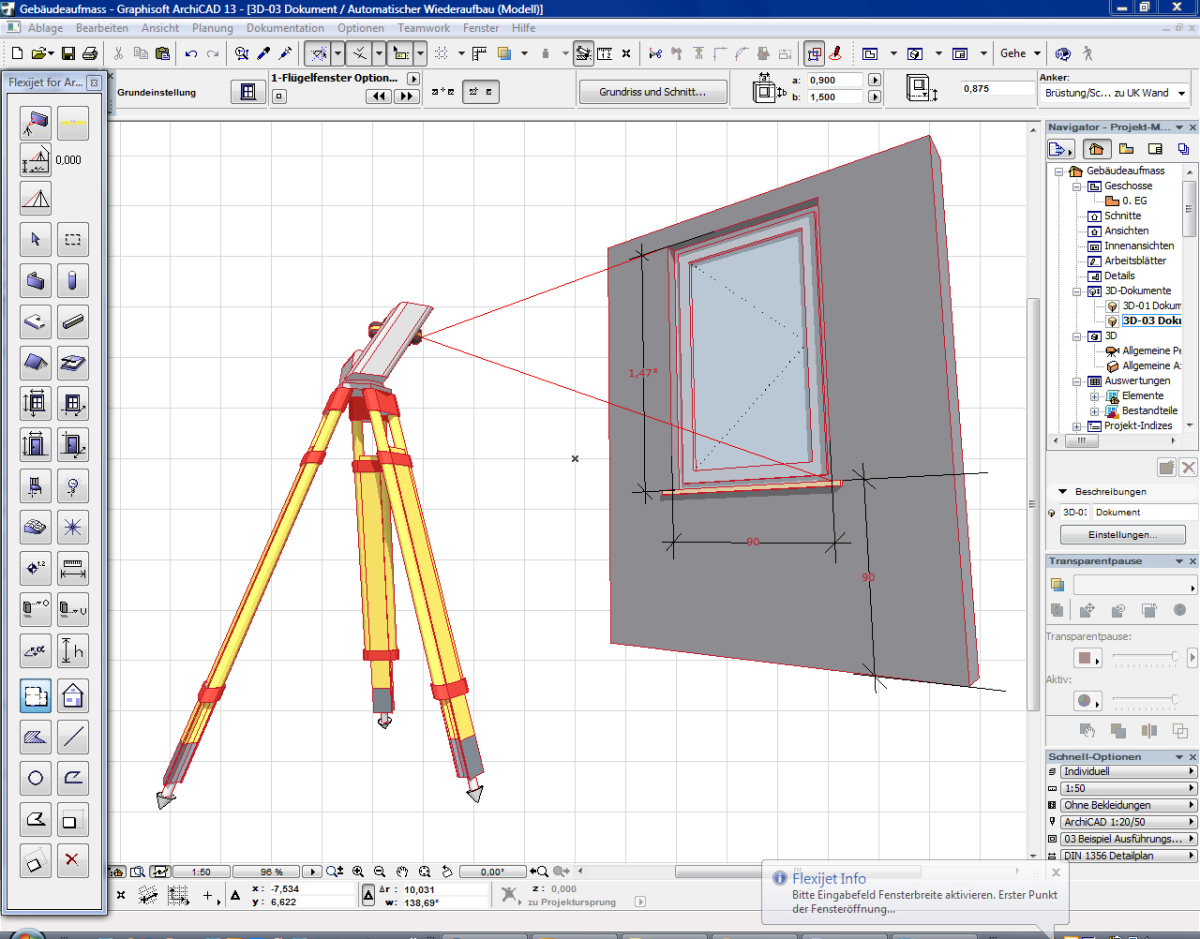 Figure: Flexijet
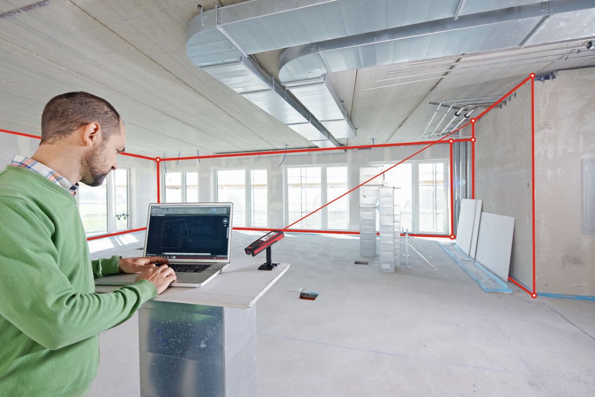 Figure: Flexijet
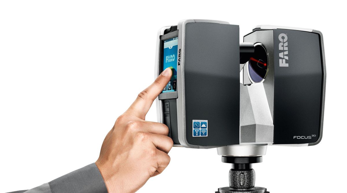 Figure: Faro
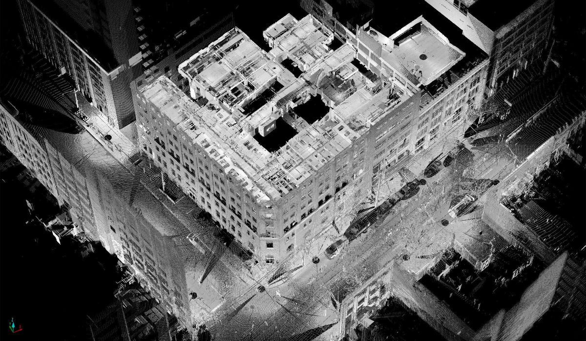 Figure: Faro
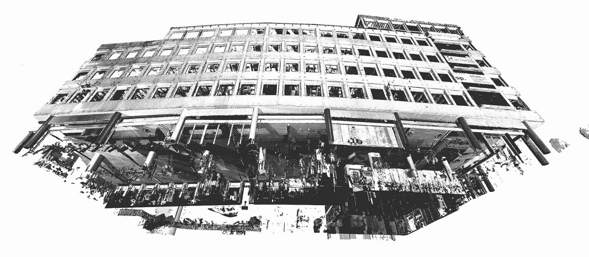 Figure: Laser Scanning Architektur
 Figure: Laser Scanning Architektur
 Laser Scanning Architektur
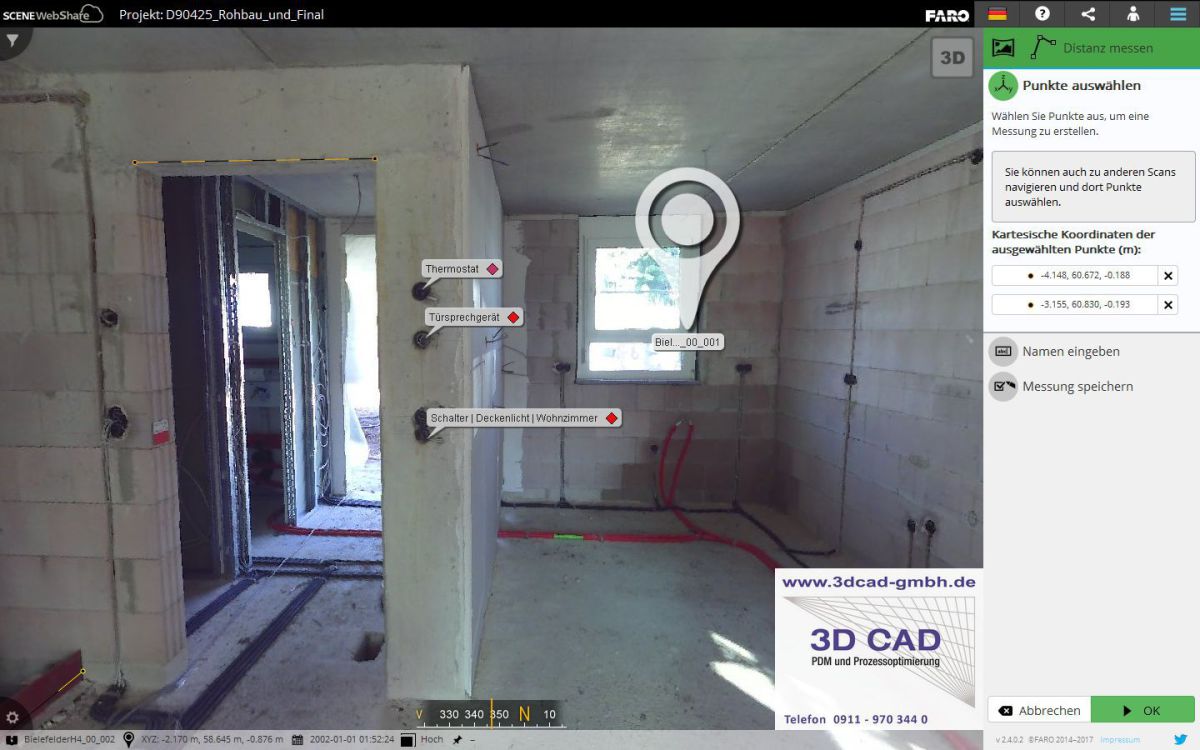 Figure: 3D CAD GmbH
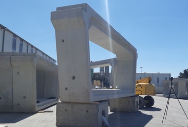
Complex geometries? Curved angles? Inclined walls and floors? Laser-assisted 3D measurement systems even capture sophisticated objects precisely and in compliance with BIM, too, as required.
Even though it is relatively easy to measure rectangular rooms or buildings with the aid of a tape measure, folding yardstick or laser distance meter, these devices completely reach their limits when it comes to complex objects, curved and inclined or free-form rooms. Specific, laser-assisted 3D measuring systems are much better suited in such cases. They capture 3D measuring point coordinates of any object using the horizontal and vertical angle as well as the measured distance. Afterwards, the digital measuring data can be transferred to mobile or desktop computers for evaluation. 3D...