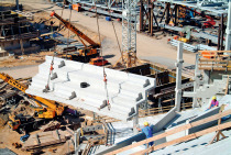
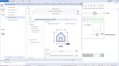
Precast CAD: Planning, presenting and producing efficiently
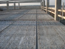
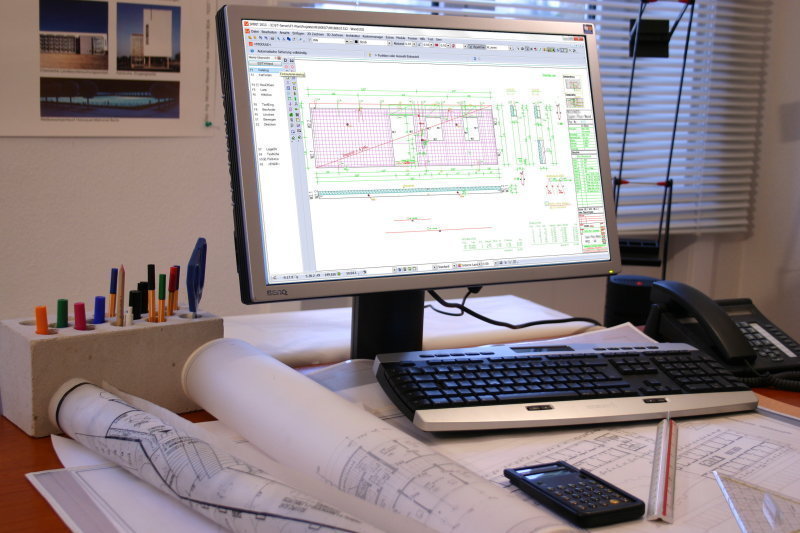 Photo: W. Riemenschneider
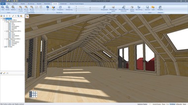
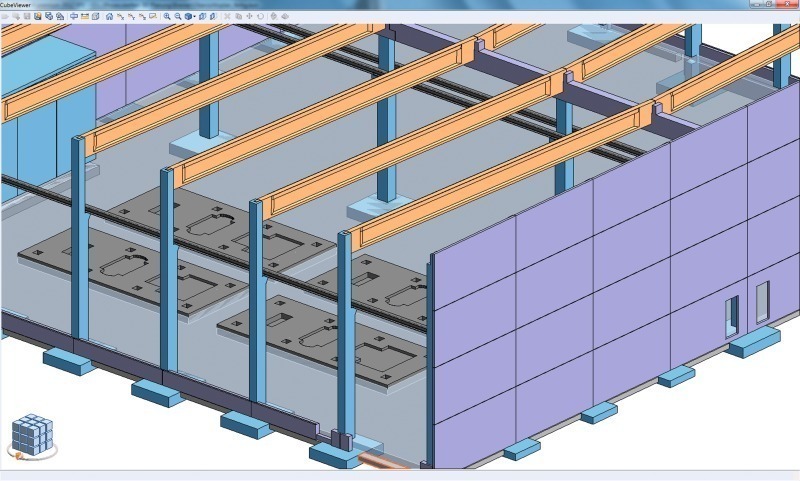 Photo: DICAD
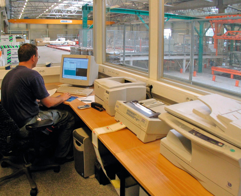 Photo: Unitechnik
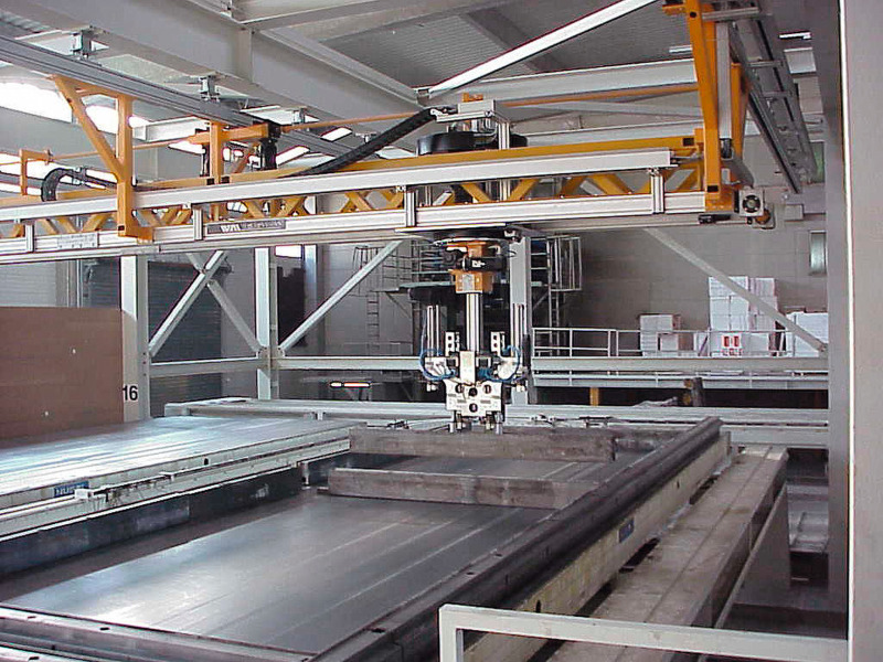 Photo: Unitechnik
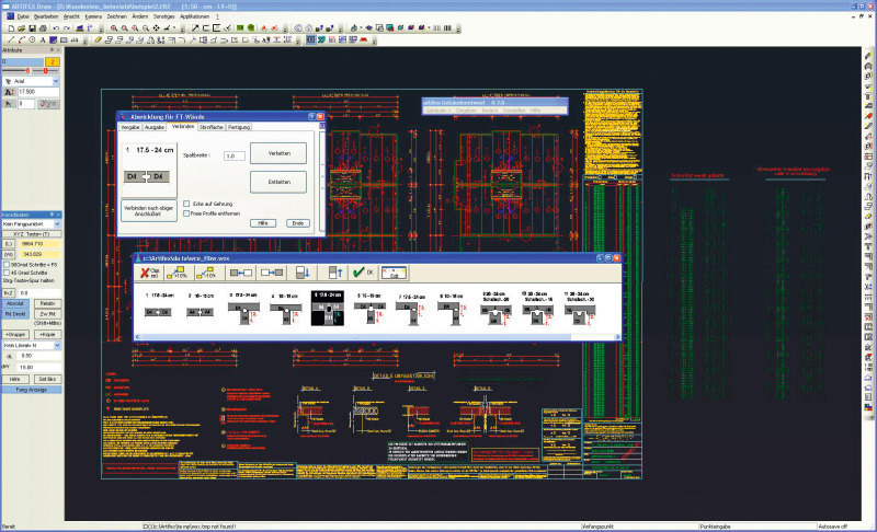 Photo: Wellcom Software
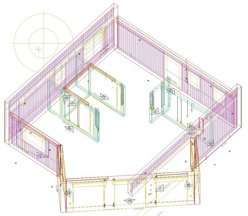 Photo: BauBIT
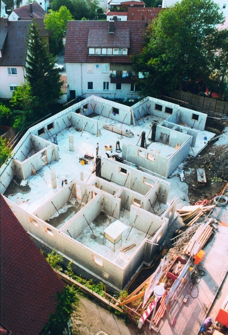 Photo: BauBIT
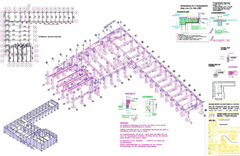 Photo: Nemetschek Engineering
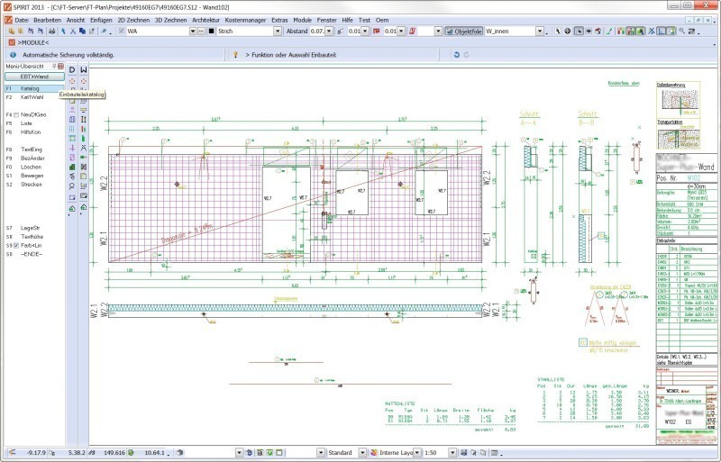 Photo: BauBIT
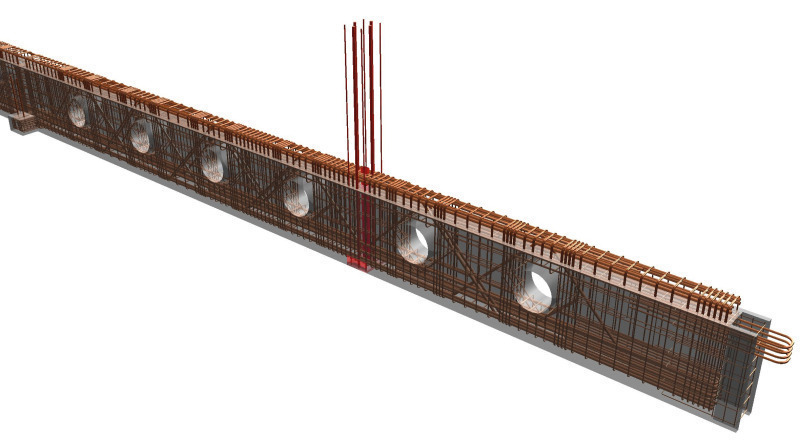 Photo: Nemetschek Engineering
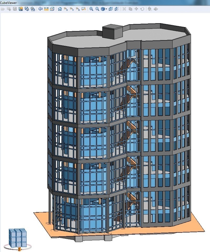 Photo: DICAD
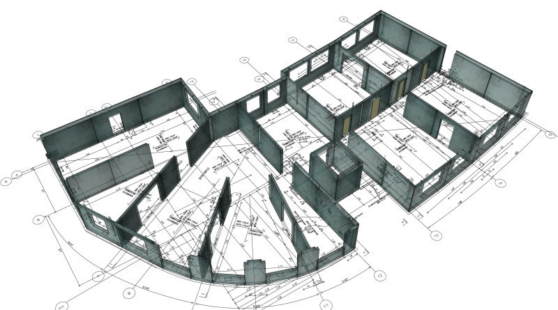 Photo: Nemetschek Engineering
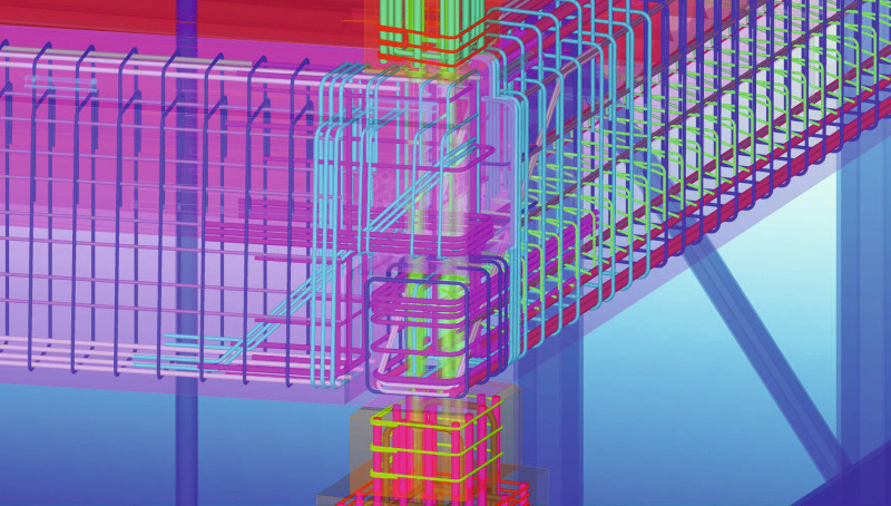 Photo: Tekla
When using the degree of automation as a yardstick, the precast industry is spearheading the trend in the construction sector. There is hardly any other sector in which the interlinking of digital design and production data is equally far advanced. This article reports on CAD and CAM opportunities, trends and developments.
In the past few years, prefabrication and precast construction have become increasingly significant. One of the main reasons why this happened is the increased cost and time pressure associated with the erection of buildings and structures. Precast elements can be manufactured for a wide range of applications quickly and efficiently in almost any conceivable dimensions, shapes, colors and surface textures. Series production increases cost efficiency and manufacturing quality but also reduces production and construction times. Industry-specific software has been used for many years at precast...