Anchorless fastening channel – redesigned and verified
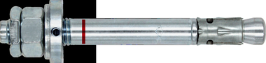
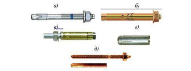
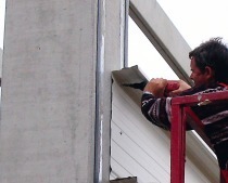
![Fig. 1: Profiled metal sheet façade fastened in a JTB-uni lightweight channel with anchors [PCN1998]](https://www.bft-international.com/imgs/2/0/7/5/1/0/5/Bild_1-8c7ca8ea0b29db3e.jpeg) Figure: PohlCon
Figure: PohlCon
 Figure: PohlCon
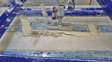
![Fig. 3: Concrete failure cone of an undercutanchor [ELI1994] (left) and an anchorless JTB-LA channel (right)](https://www.bft-international.com/imgs/2/0/7/5/1/0/5/Figure_3-ccec53f1223b850f.jpeg) Figure: PohlCon
Figure: PohlCon
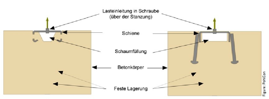 Figure: PohlCon
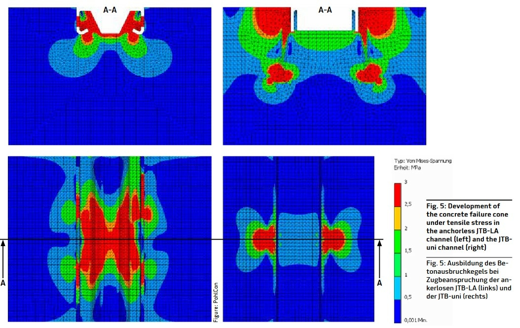 Figure: PohlCon
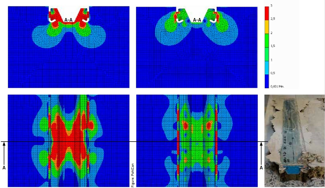 Figure: PohlCon
 Figure: PohlCon
 Figure: PohlCon


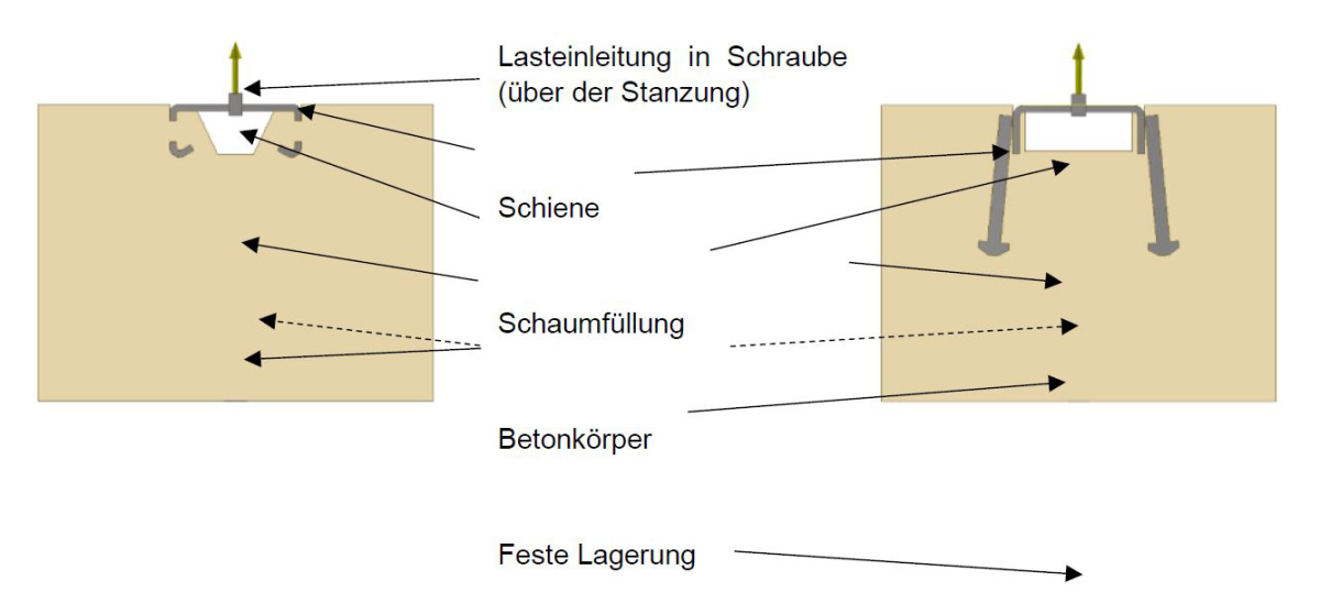 Figure: PohlCon
With increasing load requirements and, at the same time, significantly reduced installation space, products for load application must be developed which meet the requirements without the need for deep anchoring. The recently approved anchorless JTB-LA fastening channel from Pohlcon allows loads to be applied to much more slender precast concrete elements.
With increasing load requirements and, at the same time, significantly reduced installation space, products for load application must be developed which meet the requirements without the need for deep anchoring. In addition, material and resource savings are increasingly becoming a must in requirements specifications along with typical parameters such as the transferable forces. The recently approved anchorless JTB-LA fastening channel from Pohlcon allows loads to be applied to much more slender precast concrete elements, thus minimizing the design effort and increasing creative freedom.
Knowl...