Geothermal Segments: The Tunnel as Heat Supplier
 Figure: Rehau/Züblin
 Figure: Rehau/Züblin
 Figure: Rehau/Züblin
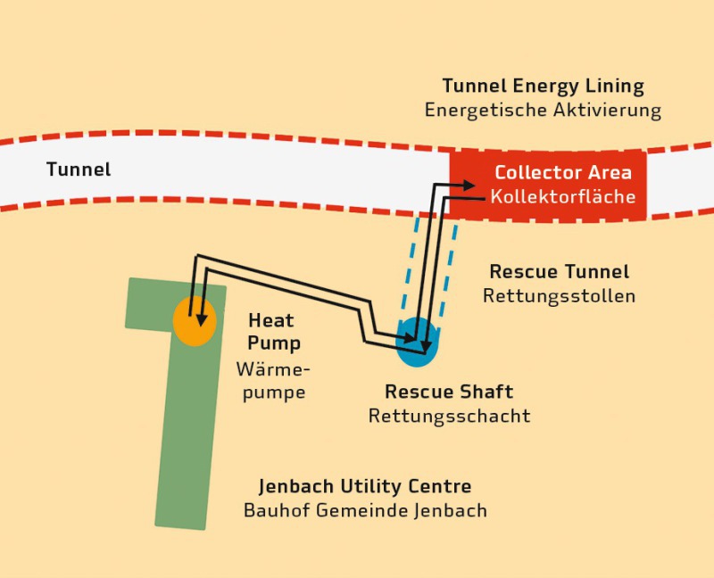 Figure: Rehau/Züblin
 Figure: Rehau/Züblin
 Figure: Rehau/Züblin
 Figure: Rehau/Züblin
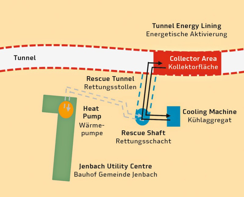 Figure: Rehau/Züblin
 Figure: Rehau/Züblin
 Figure: Rehau/Züblin
 Figure: Rehau/Züblin
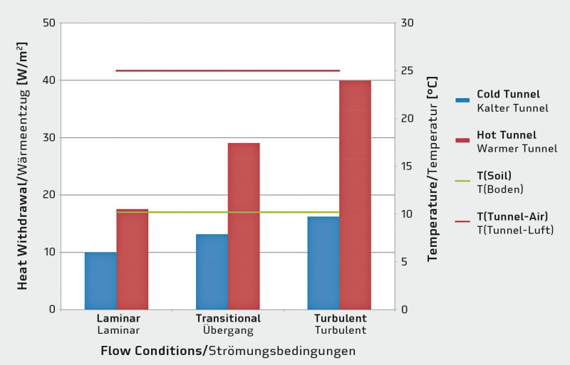 Figure: Rehau/Züblin
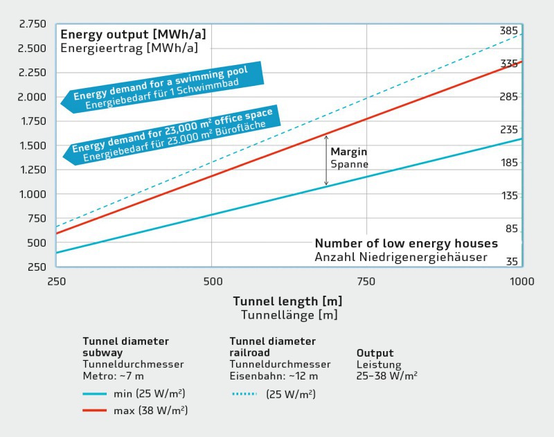 Figure: Rehau/Züblin
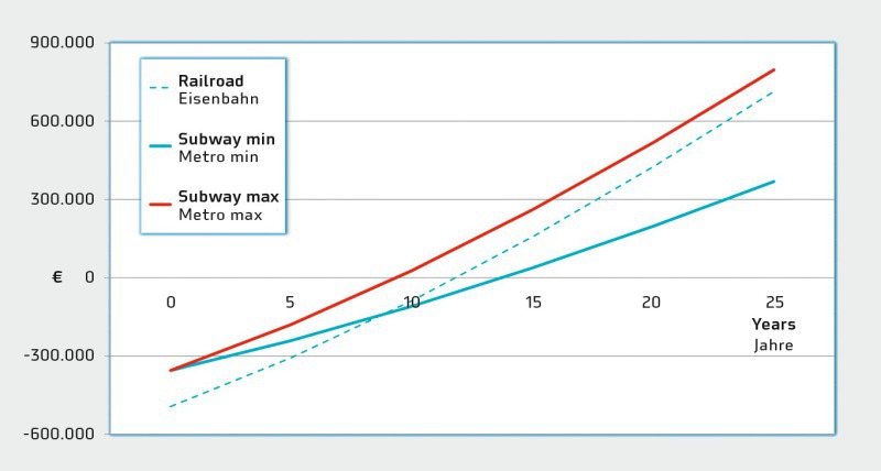 Figure: Rehau/Züblin
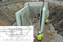
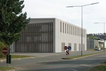
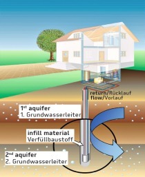
In the course of the upgrading of the railway route from Munich to Verona, a part of a tunnel in the area of Jenbach in the Tyrol has been thermally activated. It now supplies geothermal energy to the nearby utility centre.
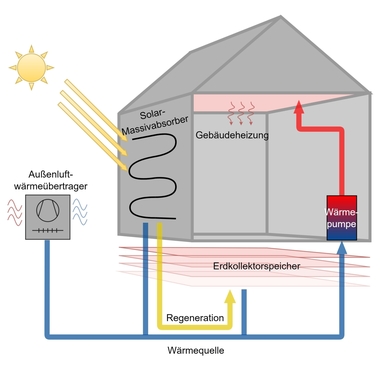
Thanks to the logging of data from the operation of the Jenbach thermal power plant since 2012, and also from additional tests, it is now possible to make more detailed statements about the energy potential and opportunities of energetic activation. The heat, which in this case is extracted from quite a shallow depth, is used for heating and cooling purposes in buildings and transport structures with a potential extraction rate of 25 to 40 W/m². It has been demonstrated that the payback period is of the same order as normal geothermal plants.
Introduction
Civil engineering structures in contact...