Analysis of Load-Bearing and Deformation Behavior of Sandwich Elements
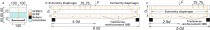
![Fig. 1 Composition of a cavity wall element with GRP anchors [7].Abb. 1 Aufbau eines Hohlwandlementes mit GFK-Ankern [7].](https://www.bft-international.com/imgs/103947832_08a4c0ac1d.jpg)
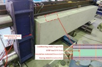
![Fig. 2 Overview of possible deformation figures of a sandwich element [9].Abb. 2 Übersicht über die möglichen Verformungs-figuren eines Sandwichbauteils [9].](https://www.bft-international.com/imgs/103947821_d3480e6571.jpg)

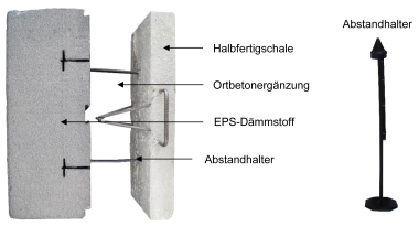
![Fig. 5 Approximate load-deformation curves for polystyrene used as an insulating material (cf. [6]).Abb. 5 Approximierte Kraft-Verformungs-Beziehungen für den Dämmstoff Polystyrol (vgl. [6]).](https://www.bft-international.com/imgs/103947866_3154e40cd0.jpg)
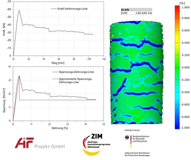
![Fig. 9 Set-up of the component test [7].Abb. 9 Versuchsaufbau des Bauteilversuches [7].](https://www.bft-international.com/imgs/103947820_9f5820deb0.jpg)

Sandwich elements can be produced quickly and cost-efficiently under the favorable conditions provided at the precast plant, and they conform to highest concrete quality standards. These are compelling arguments in favor of this method compared to cast-in-situ construction. However, a realistic representation of the load-bearing behavior of sandwich elements is complex, which is why it is not usually carried out in the practical design of elements. This article presents a computation model for sandwich elements and derived findings that were included in a thesis submitted to the Institute of Concrete Structures and Structural Engineering (Prof. Dr.-Ing. J. Schnell) at Kaiserslautern University of Technology.
Load-bearing behavior of sandwich elements
The load-bearing behavior of random, layered structural components is determined by the stiffness of the individual layers and by the type and extent of joint actions of these layers.
Compared to the relatively rigid covering layers of sandwich elements made of concrete, the contribution of the insulation layer to their overall load-bearing capacity can be largely neglected. However, the insulating layer creates a shear bond between the covering layers by means of interlocking and/or adhesion, which is why bending moments acting on the overall cross-section are partially transformed to a couple of forces acting on the covering layers. The magnitude of this sandwich effect (structural diaphragm effect) is determined by the shear stiffness of the core layer and can be influenced by specific interventions.
The load-bearing behavior of a sandwich element with a very flexible core layer is equivalent to the behavior of covering layers loosely placed upon each other. The reverse case results in rigidly connected upper and lower chords, which leads to the high rigidity known from I sections (Fig. 2). Due to the complex structural effect, the serviceability and ultimate limit states occurring in sandwich elements are more diverse than in homogeneous structural components. Serviceability limit states occur in relation to deformation patterns and crack widths whereas the ultimate limit state may be determined by the failure of one of the layers or of the entire layer bond.
Generally applicable computation approach using energy methods
Energy principles provide the basis for analytical methods used in structural engineering. A specific approach results from applying Lagrange’s principle of the minimum of potential energy: Of all kinematically possible deformations of the system, those will occur for which the total potential P becomes a minimum.
P = Pi + Pa ➝ Minimum(1)
Determination of internal potential energy Pi
The work W (strain energy per unit volume) of the internal forces performed during the deformation of an elastic cross-section corresponds to the integration of the stresses over the related strains.
The internal potential energy of a structural framework is the result of the integration of the strain energy per unit volume over the entire framework. For the
purposes of the calculation, the structural framework needs to be sub-divided into load-bearing components (index E), cross-sections (Q) and cross-sectional segments (layers S).
Pi(E) = ∫L Pi(Q) dx = ∫L Σ Pi,el(S) dx = (2)
∫L Σ ∫AS,i ∫0e x (σ (ex)) dex dAS + ∫AS,i ∫0γ (τ (γ)) dγ dAS dx
Rigid layers absorb a high amount of strain energy per unit volume through strains acting on them but are subjected to very minor shear deformation with negligibly small energy portions. Conversely, flexible layers take up hardly any normal stresses due to their low modulus of elasticity but contribute a considerable amount of strain energy per unit volume because of significant shear deformation (cf. [9]).
Determination of external potential energy Pa
At the cross-sectional level, the external potential energy is the product of the internal force and the related strain of the cross-section:
The transfer to the structural framework level is made in analogy to the internal potential energy, i.e. by integration over the entire length of the structural component (Equation 3). This formula expresses the external potential as the displacement of forces along their lines of action.
Pa(E) = ∫L Pa(Q) dx = – Σ (Nj · uj + Qj · wj) =
Σ ( ∫qz,j · dxi ) · wj + ( ∫qx,j · dxi ) · uj (3)
Quick resolution of the optimization task using MS Excel
Mathematical optimization is concerned with the analysis of composite functions regarding any minima and maxima that constitute optima under certain preconditions. An optimization problem can be captured mathematically if the objective can be expressed unambiguously as a function of one or several parameters (variables). This function is termed objective function. If the variables need to also fulfil equality or inequality conditions, these are referred to as side conditions.
In this case, the objective function is equivalent to Lagrange’s principle of the potential energy minimum (Equation 1) whereas deformations are varied. Side conditions comprise compatibility and boundary conditions. Compatibility conditions result from the specification of cross-sectional segments with retained evenness, as well as continuous strain levels. Boundary conditions result from the structural system.
The input of the above general conditions into an Excel spreadsheet provides an input screen to which the user needs to add only the geometry of the element and its loading. The optimization task is solved “at the push of a button” using the Solver optimization algorithm integrated in the Excel package.
Reflection of the material characteristics
The calculation of the strain energy per unit volume uses the load-deformation laws of the materials included in the cross-section as a key parameter. The computation model relies not only on the material laws for concrete and reinforcing steel, which have been subject to comprehensive research, but also on approaches to reflecting the material behavior of the insulating layer.
The stress-strain curve of concrete as a composite material shows a very different pattern in compression and tension, with its tensile strength being considerably lower due to the brittle bond between the cement paste and the aggregate particles. In the computation model presented in this article, the term developed by Grasser [2] specified in DIN 1045-1 is used for the compression side. This term closely reflects the non-linear progression of the stress-strain curve on the compression side.
We get the approximate stress-strain curve of concrete in tension in State I by using a polynomial function (cf. [4]). In State II, cracked cross-sectional segments of the concrete are stress-free. The contribution of the concrete between the cracks is reflected by modifying the stress-strain curve of reinforcing steel (see below).
Steel shows a virtually identical behavior in compression and in tension. In the computation model, the stress-strain curve of steel is described by a bilinear equation (as specified in DIN 1045-1), which delivers sufficiently accurate results.
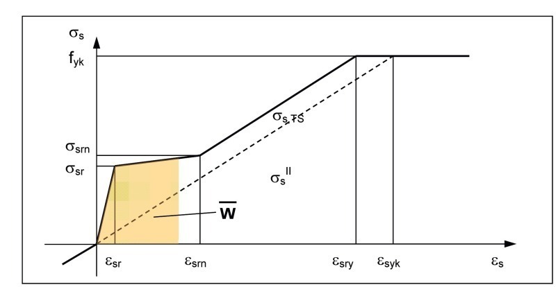
For cracked reinforcing steel cross-sections, the modified stress-strain curve of reinforcing steel is used in conjunction with the “smeared crack model” (Fig. 3). In this approach, a mean steel stress is allocated to the reinforcing steel in such a way that the energies of contributing concrete portions located between the cracks are also considered (cf. [1]). Accordingly, the stresses of concrete areas subject to positive strain are set to zero in order not to account for the energies twice.
In the tests outlined in this article, ComBAR GRP bars supplied by Schöck were used as connecting elements between the structural shells. Compared to reinforcing steel, bars made of glass-fiber reinforced plastic provide greater elasticity but also a very high tensile strength (E modulus of approx. 60,000 N/mm², tensile strength of approx. 1,000 N/mm²). Their stress-strain curve shows a linearly elastic progression to failure. The transferability of the approach to describing the bond behavior of steel to GRP bars is demonstrated in [5].
Rigid polystyrene foam panels are used in sandwich elements for core insulation purposes. More specifically, expanded polystyrene foam (EPS, e.g. styrofoam) is considered. Due to their highly porous structure, PS insulating materials show non-linear stress-strain curves with relatively low strength parameters and a high degree of creep, which is why a contribution of the insulating material should not be considered under permanent loading.
Tests of the load-deformation behavior of the insulating layer
In the insulating layer, the more rigid GRP bars (in a punctiform arrangement) act jointly with the PS insulating material, which shows a virtually complete bond with the concrete shells. Shear tests were used to establish load-deformation relationships for both components, which create the basis for determining the energy portions attributable to the insulating layer.
The tested specimens consisted of two external concrete shells with an internal insulating layer of varying thickness (Fig. 4). GRP bars and PS insulating materials were tested individually in various set-ups. Non-displacement perpendicular to the shell plane was ensured in accordance with the recommendations given in DIN EN 12090. Results of the shear tests included the measured shear paths and the compressive forces required for this purpose. The load-deformation law allocates the unit stress t to the shear angle g of the shearing unit deformation.
The resulting material laws were verified by re-analyzing tests where the insulating layer included both the insulating material and GRP anchors. For this purpose, the calculated shear stress resultants of anchors and insulating material were superposed. The resultant was equivalent to the compressive force measured in the test.
Load-deformation law for expanded polystyrene foam (EPS)
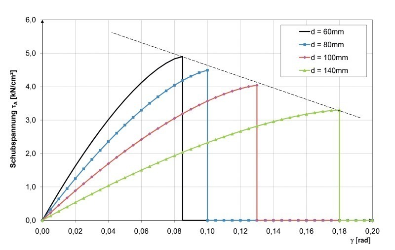
The load-deformation behavior of the insulation panel in shear is characterized by a curve that shows a non-linear rise until the shear strength is reached, followed by a residual shear strength that is constant at a low level (Fig. 5). The polystyrene panels exhibit a roughly uniform tangential shear modulus (GD ≈ 0.25 kN/cm²) and higher shear strengths at lower layer thicknesses, which leads to the thickness-dependent parameters in Table 1.
Non-linear material law (power function):
where 0 ≤ γ ≤ γD,pl
t(γ) =
t(γ) = tD,res = const. where γD,pl < γ(4)
where kD = 1.41
Load-deformation law for GRP anchors
For the anchors, the following general load-deformation equation was found in tests.
Non-linear material law (power function):
t(γ) = nA ∙ tA,max ∙ 1 – ( 1 – –––– )(5)
where kA=1,5
The GRP anchors become more flexible as the thickness of the insulating layer increases (Fig. 6), which is probably due to the possibility of an increasingly significant redistribution of stresses as a result of an increase in anchor length.
Calculated example of a single-span sandwich beam
As the system to be calculated, a single-span beam supported in a statically determinate manner was selected, which simulates the frequently occurring case of a full-story sandwich wall that is supported at its top and bottom edges. The actions resulting from temperature and area loads were varied, as were the component dimensions and material strengths. The analysis was conducted on the basis of the deflection, shear deformation and internal force curves established in the computation model.
In a first step, the plausibility of the calculation results can be checked conveniently using the computed figure of deformation of the structural component (Table 3).
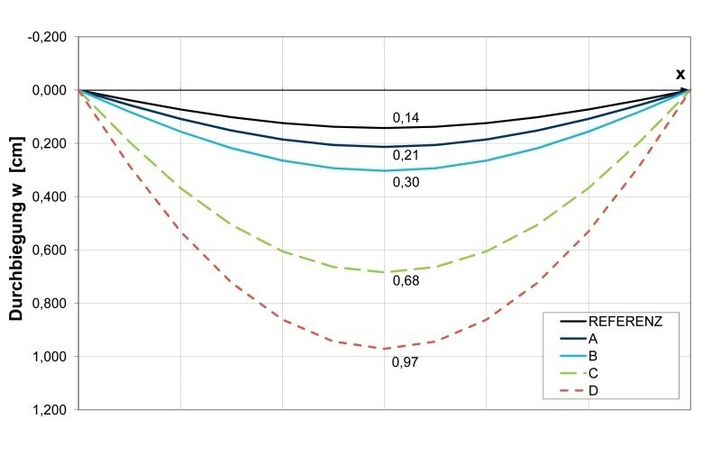
Qualitative comparison of deformations
An uncracked sandwich cross-section with a 15 cm thick structural shell, a 10 cm thick insulating layer and a 6 cm thick curtain walling is used as a reference (cf. Fig. 7). The elimination of the shear stiffness of the insulating layer results in a 50% increase in deflection. A 50% reduction in the thickness of the structural shell even leads to a 100% increase in deflection, which means that the shell thickness has a disproportionately significant effect on the deformation of the structural component.
In addition, the lower curves show the crack-induced degradation of stiffness very clearly. In State II, deflection increases to four times the original value when considering the contribution to tension of the concrete areas between the cracks. If the tension-stiffening effect is not considered, deflection would again increase by 50% in the case at hand.
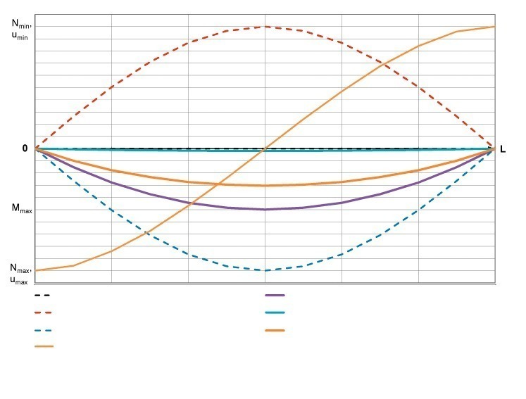
Also of interest is the displacement of the concrete shells relative to each other (Fig. 8) because this parameter directly captures the design-relevant deflection of the structural components within the insulating layer. In addition, element dimensions and façade joint dimensions can be derived from this value.
Output of internal forces
The calculation results can be verified using the total bending moment at mid-span and the symmetry of the internal force curves. The “sandwich effect” manifests itself by the build-up of normal forces in the concrete shells and by the intrinsic bending moments of the shells, which are lower compared to the total bending moment (Fig. 8).
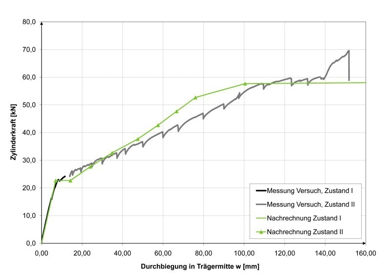
Recalculation of component tests performed for sandwich elements
As part of the research, component tests for more extensive complete sandwich elements were also carried out at the structural engineering laboratory at Kaiserslautern University of Technology (Fig. 9).
The recalculation reveals a strong equivalence of the load-deformation curves in the linearly elastic range. The point in time at which the transition to State II occurs is also captured adequately (Fig. 10). The rigidity in State II is slightly greater in the recalculation, which is mainly influenced by the reinforcing strands and the tension-stiffening effect.
Summary and outlook
The expression of the state of deformation of the structural component as an optimization problem using energy methods generally enables the analysis of composite structural components. The calculation approach can be applied to cross-sections of a largely variable composition. It is flexible with respect to the type of loading and support of the structural component.
The stress and deformation states of reinforced concrete sandwich elements (which were in the focus of this research) can be determined with a high degree of accuracy using the calculation approach presented in this article. The basis for this calculation is provided by an accurate reflection of the load-deformation behavior, in particular of the core layer subject to shear. The correct capturing of the actual load-deformation behavior was demonstrated by recalculating a component test carried out at the structural engineering laboratory at Kaiserslautern University of Technology.
As a result, more accurate parameters are available for the design of reinforced concrete sandwich cross-sections, which can provide a higher degree of safety and open up opportunities for a more economical design. In addition, conclusions can be drawn with respect to the occurrence and effect of cracking in the concrete shells.
The computation models to be used for the analysis of the cross-section or structural component were largely designed in Excel applications to provide an easy-to-use interface. They can be integrated as modules in comprehensive VBA programs. Thus a user-friendly, variable tool can be made available for analyzing composite structural components or for establishing design tables.