Historic Stellenbosch Bridge rebuilt with precast concrete beams
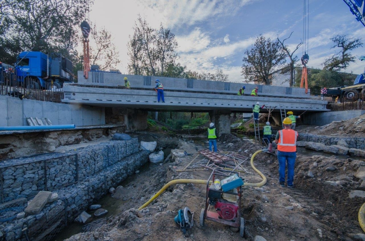 Figure: David Beer
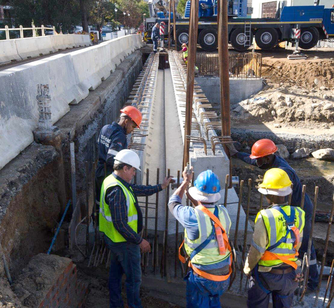 Figure: David Beer
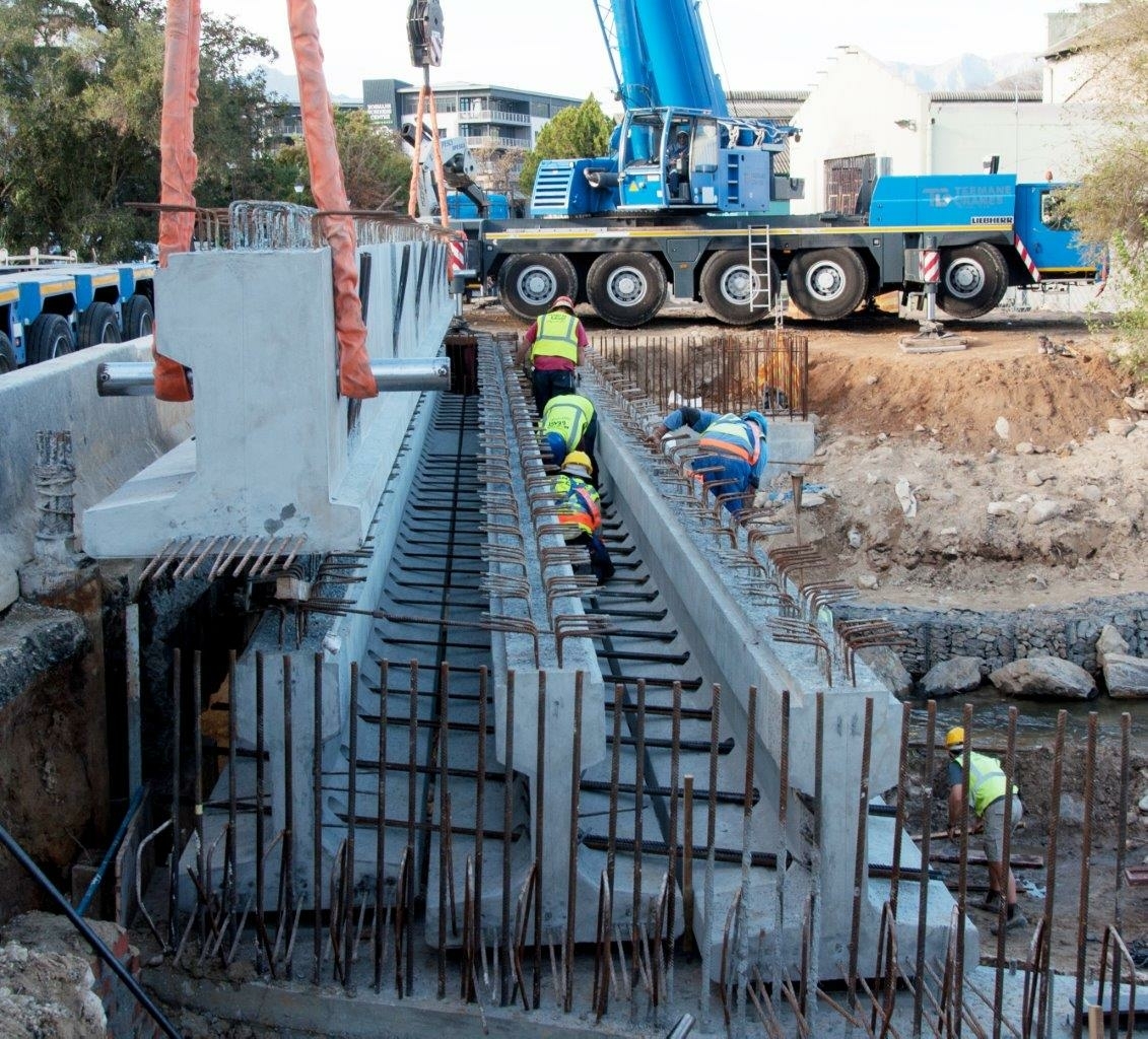 Figure: David Beer
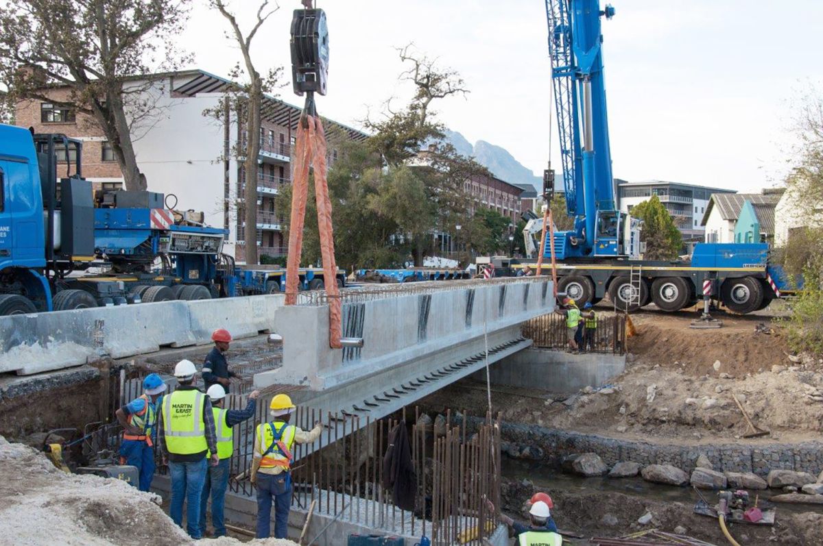 Figure: David Beer
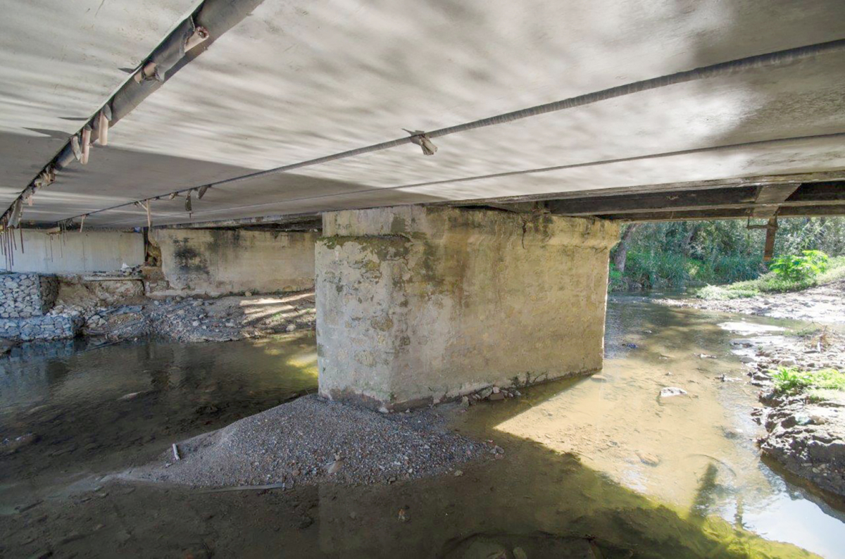 Figure: David Beer
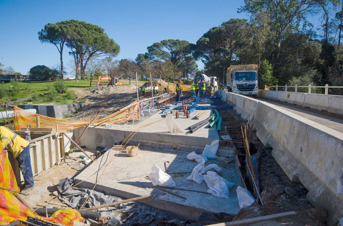 Figure: David Beer
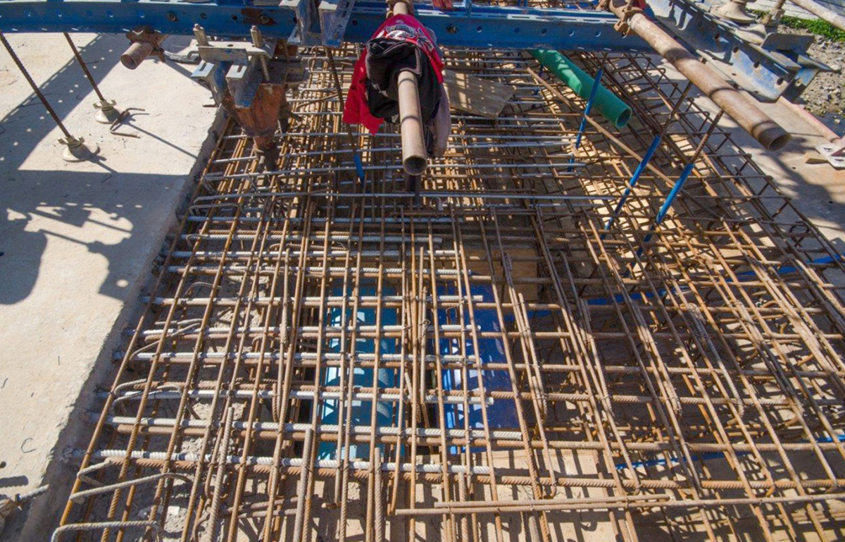 Figure: David Beer
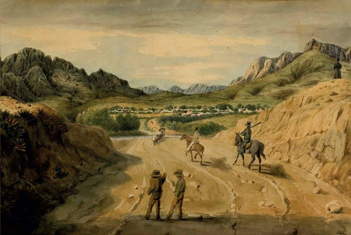 Figure: Collections of Parliament Cape Town
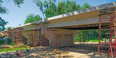
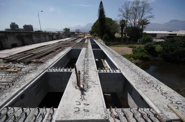
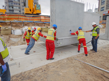
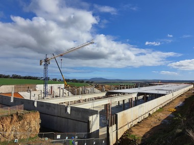
The old bridge over the Plankenbrug River (formerly Dwars River) in Stellenbosch, South Africa, has been rebuilt by Martin & East (Pty) Ltd with nine precast concrete beams supplied by Concrete Manufacturers Association member (CMA), Cape Concrete.
The old bridge over the Plankenbrug River (formerly Dwars River) in Stellenbosch has been rebuilt by Martin & East (Pty) Ltd with nine precast concrete beams supplied by Concrete Manufacturers Association member, Cape Concrete. Designed by infrastructure consultancy AECOM SA (Pty) Ltd, the first phase of this two-phase project was completed in August 2022 and the second in February 2023.
The new bridge will provide improved access to Bosman’s Crossing, a burgeoning residential, commercial and light-industrial precinct situated in the old KWV Industrial Park immediately east of the bridge.
The...