Thermal anchor for carbon-fiber reinforced concrete double walls
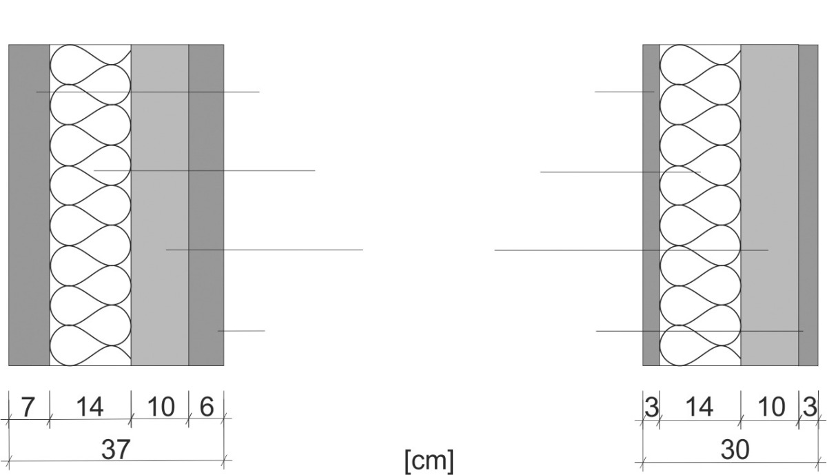 Figure: Juliane Wagner
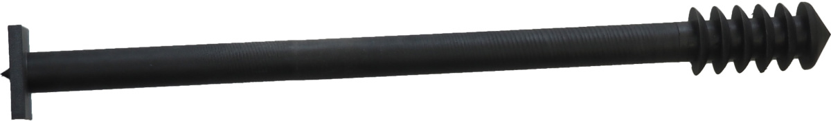 Figure: Juliane Wagner
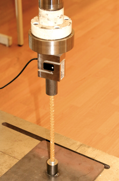
![3 Fixing of the thermal anchor with a clip [4]](https://www.bft-international.com/imgs/1/4/0/9/2/5/0/Bild_3-c82868933028e90c.jpeg) Figure: Juliane Wagner
Figure: Juliane Wagner
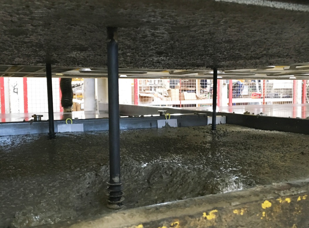 Figure: Juliane Wagner
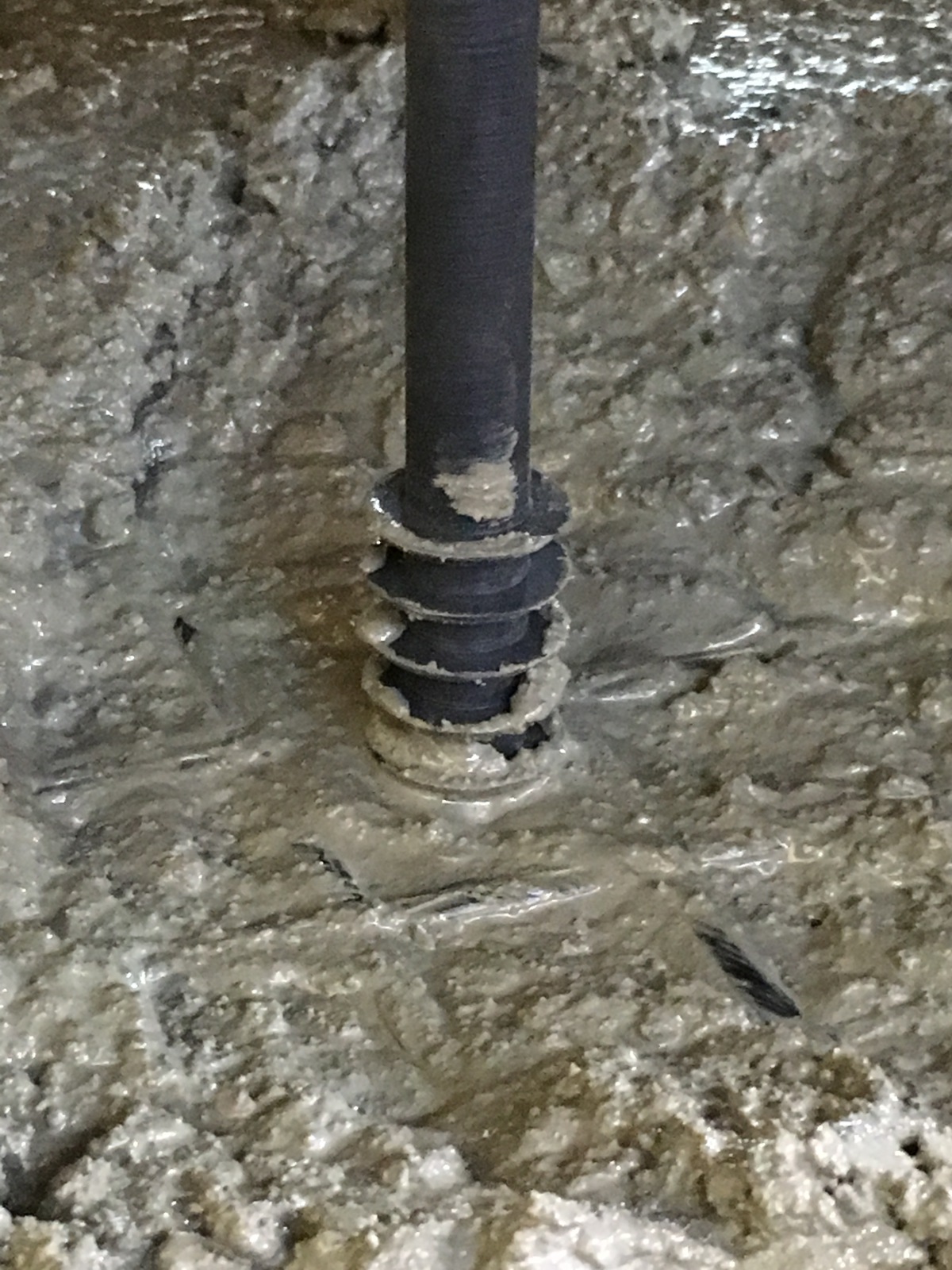 Figure: Juliane Wagner
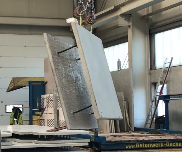 Figure: Katrin Mende, HTWK Leipzig
![7 Expected effects: a) axial force, b) transverse shear pull, c) axial pull [4]](https://www.bft-international.com/imgs/1/4/0/9/2/5/0/Bild_7-801f972770bc815b.jpeg) Figure: Juliane Wagner
Figure: Juliane Wagner
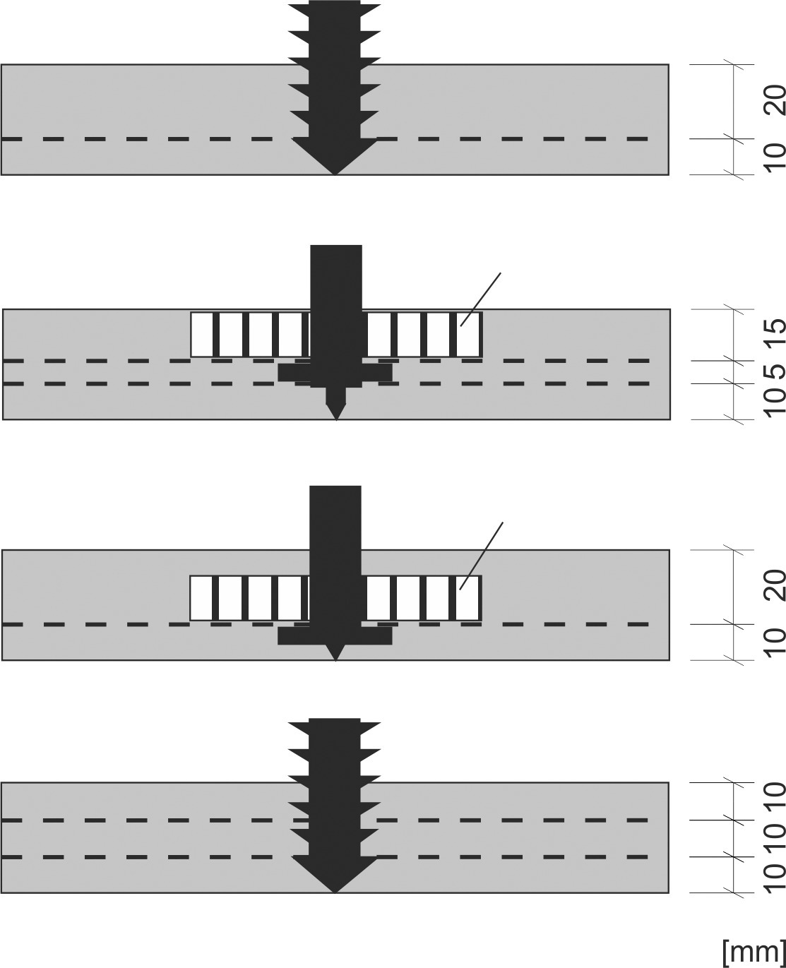 Figure: Juliane Wagner
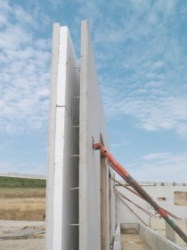
Thermal double walls can be considerably thinner and lighter if they are manufactured using carbon-fiber reinforced concrete. That means more space in the finished building and advantages for transportation to the building site. However, conventional means of connection are unsuitable for the connection of the wall shells. This paper presents a new type of thermal anchor with which the connection of the shells can be successfully accomplished.
Double walls or thermal double walls made of reinforced concrete have long been used in the precast industry. On account of their high degree of prefabrication and their function as permanent formwork on the building site, where the individual elements are connected by means of an in-situ concrete filling, the semi-precast parts have proven to be a cost-effective solution. A thermal double wall normally consists of two reinforced concrete wall shells with a thickness of 6 to 7 cm. In between them there is a layer of thermal insulation and a void to be filled with cast-in-situ concrete [1]. The...