New possibilities for measuring the humidity of concrete using cable humidity sensors
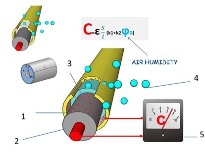 Figure: Engimatic
 Figure: Engimatic
 Figure: Engimatic
 Figure: Engimatic
 Figure: Engimatic
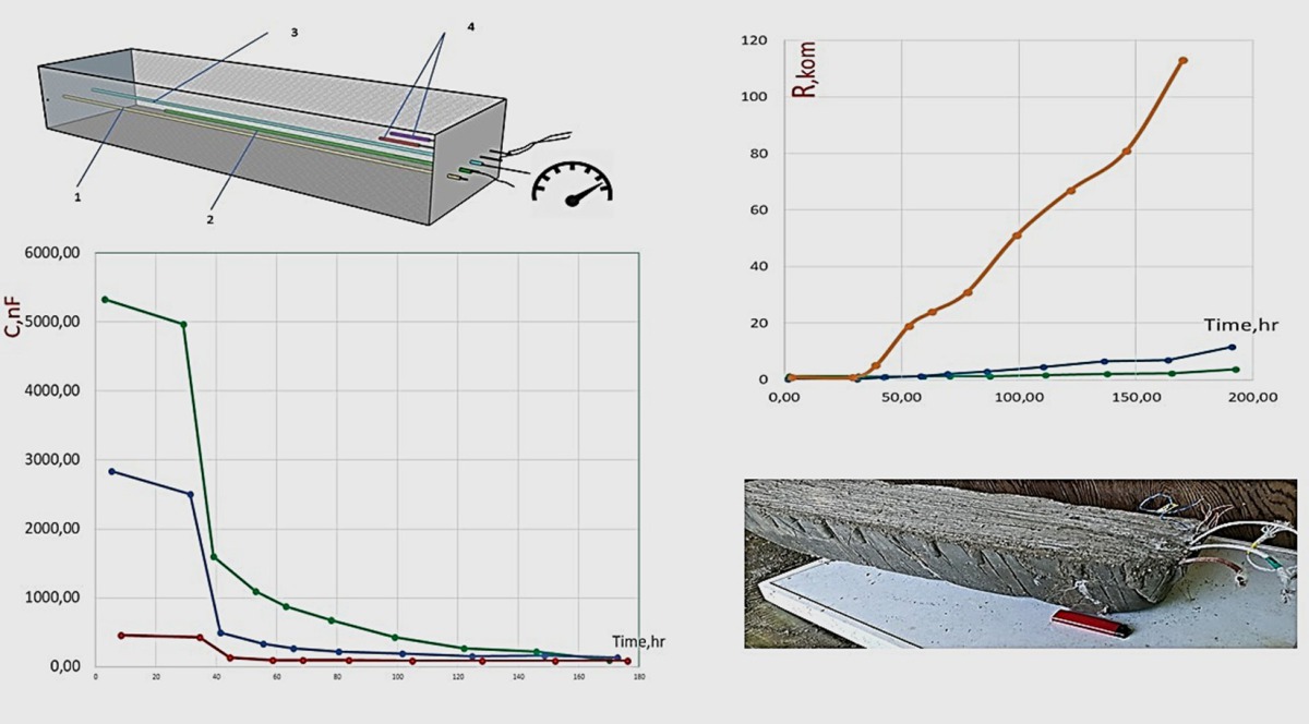 Figure: Engimatic
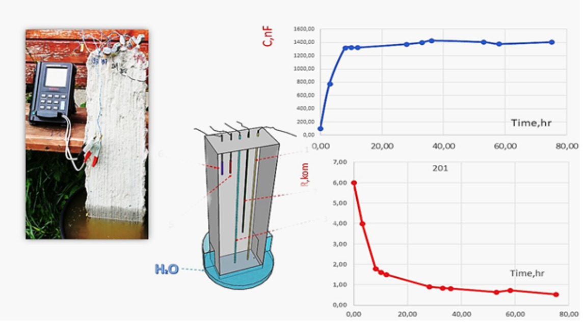 Figure: Engimatic
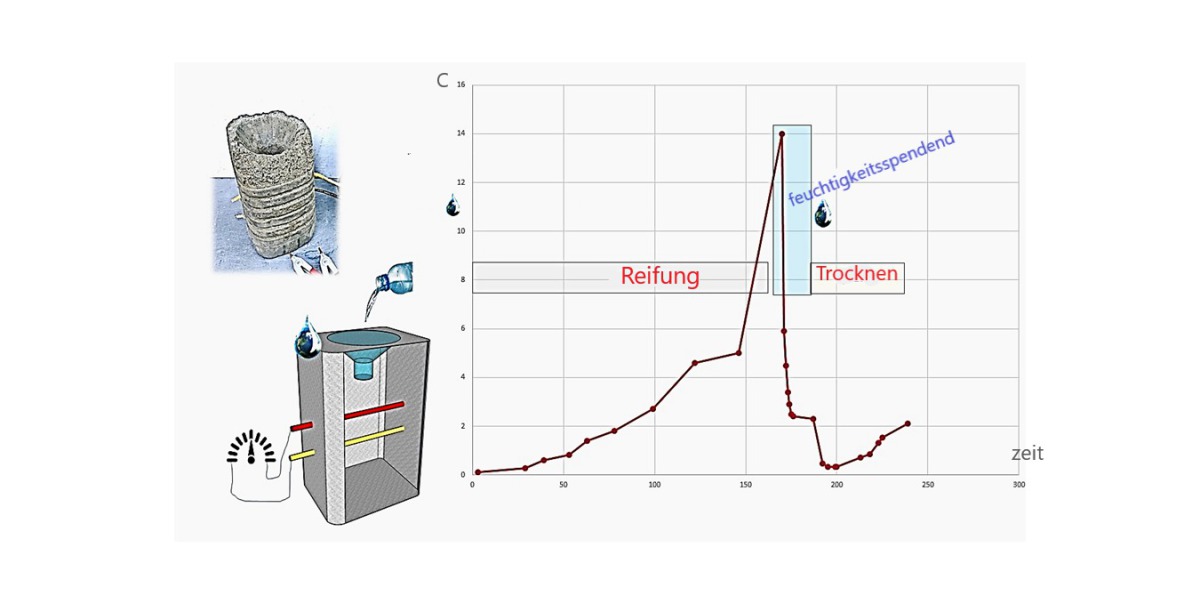 Figure: Engimatic
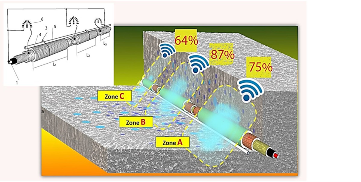 Figure: Engimatic
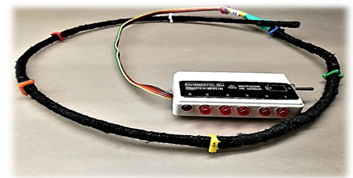 Figure: Engimatic
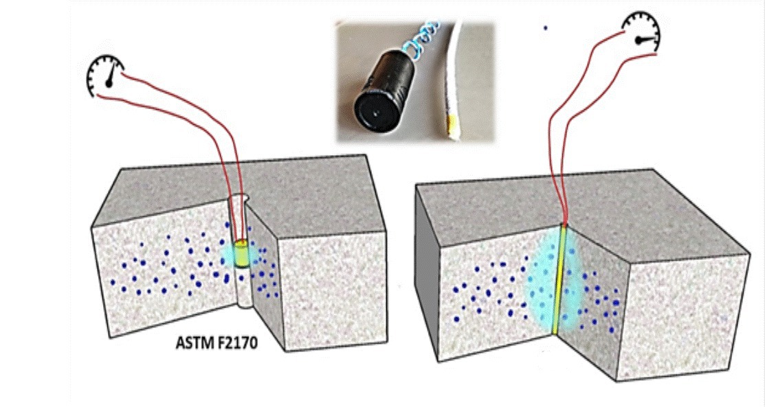 Figure: Engimatic
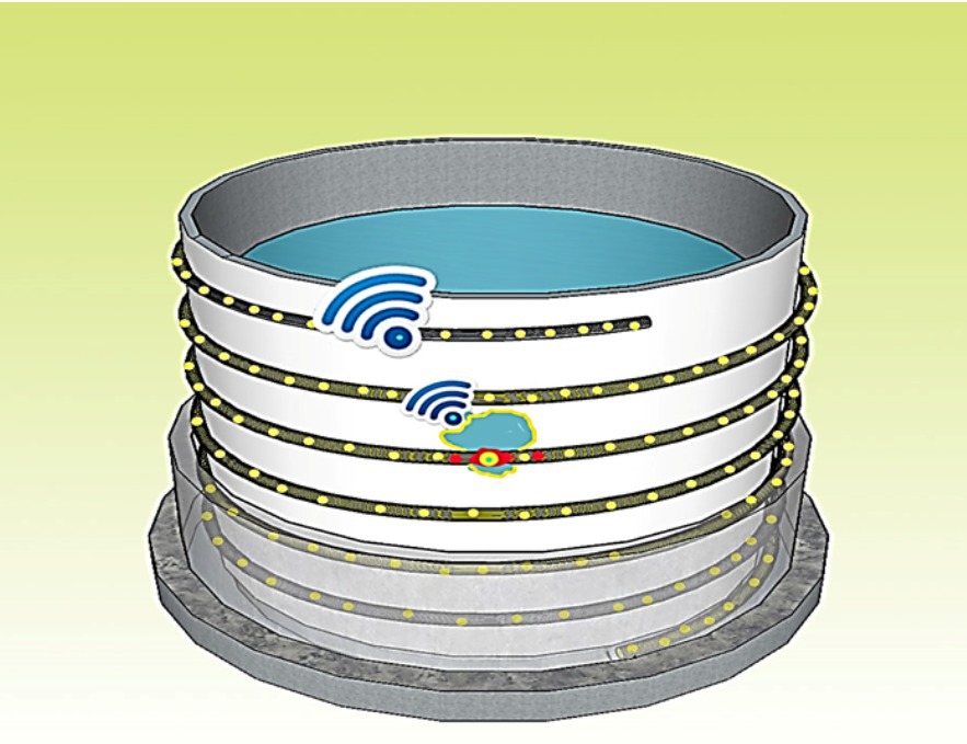 Figure: Engimatic
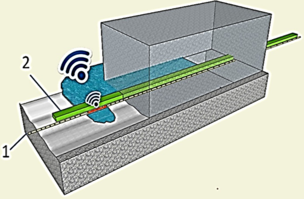 Figure: Engimatic
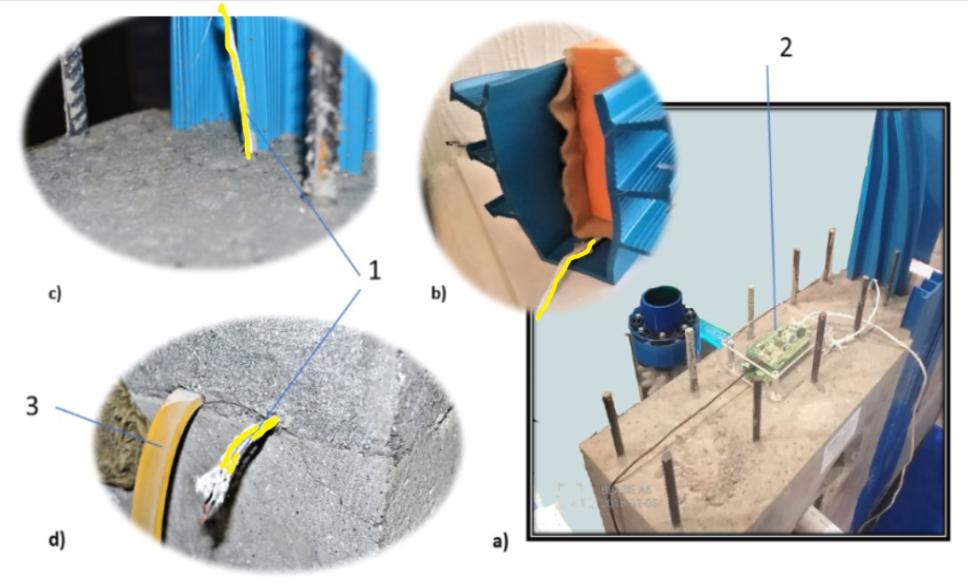 Figure: Engimatic
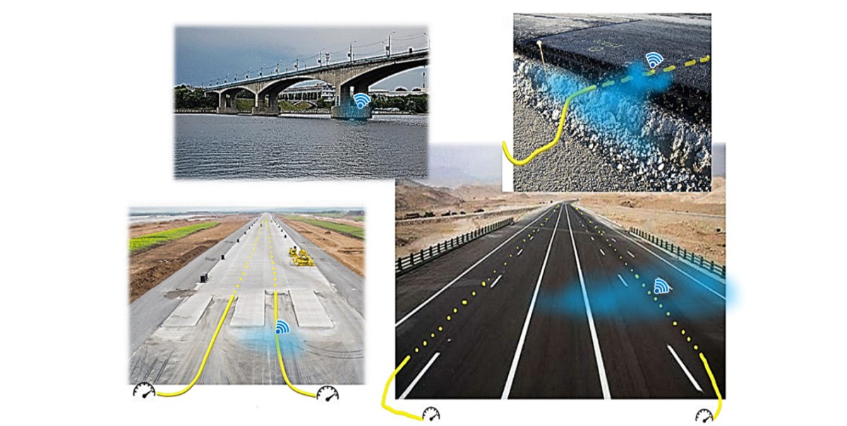 Figure: Engimatic
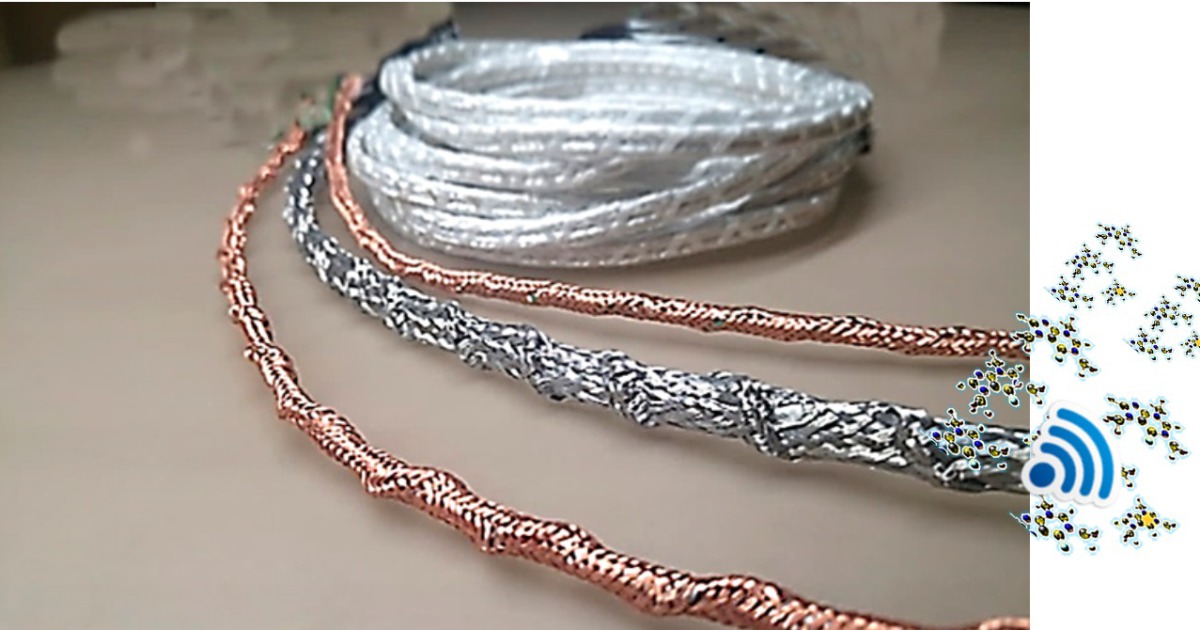 Figure: Engimatic
 Figure: Engimatic
A fundamentally new type of cable humidity sensors (also called CHS in this article) has been developed, patented and tested by Engimatic. This sensor allows the measurement of the average value of humidity inside concrete structures. It provides the possibility of online monitoring of moisture in building structures throughout the service life.
The practical significance of controlling the water content in concrete cannot be emphasized highly enough. It is sufficient to recall that it is the addition of water to the dry concrete mixture that gives rise to the actual hardening process of concrete. The kinetics of hydration and „maturing“ of concrete are directly related to changes in the moisture content. This allows the manufacturer to determine the optimum moment for stripping the formwork and to save 10 to 20% of the total costs of concreting at the same time, according to various estimates [1].
The two main natural causes for the destruction of complete building structures including concrete structures, among others, are moisture and frost. The Egyptian pyramids, if transferred to the north of Europe, for example, would not have survived there for hardly more than hundred years because of moisture and frost.
Therefore, it is obvious that the constant monitoring of the humidity regime of a concrete building is essentially one of the most important tools for extending its service life.
1 Standards for the measurement of moisture in concrete
The current national and international industry standards for the measurement of moisture in concrete can be divided into two groups – destructive and non-destructive testing.
The first group includes the most common methods of grinding, heating and weighing of standard specimens (specially cast specimens) or core samples (drilled from „original“ concrete elements). Test drillings into concrete structures also require a method (ASTM F2170). It should be noted that [2,3,4] independent small-sized sensor modules „implanted“ into a component when pouring concrete have appeared on the market recently. They continuously transmit radio channel information on air humidity and temperature measured at the point of a „bookmark“. However, their service life is limited by the service life of the batteries and, unfortunately, the information received about the humidity does not provide any complete information.
The second group of non-destructive standards includes the so-called surface measuring methods for determining the moisture content of concrete (ASTM F1869 standard). A layer of calcium chloride is applied to the concrete surface and, after some time, changes in the appearance of this chemical are recorded. Moreover, ASTM F2659 standard was developed, analyzing the „reaction“ of concrete on the testing microwave radiation. However, owing to physical limitations (water diffusion, attenuation of the microwave radiation), all these surface moisture measurement methods only work correctly in case of relatively thin surface layers of concrete of 2 to 3 cm.
Hence, the currently existing standards for moisture measurement have a one-time, one-stage character and allow determining the moisture content of concrete either at one point or in thin surface layers of concrete. In many critical cases, for example, under difficult climatic conditions of concrete curing or in cases of permanent contact with water, water vapor, moisture-containing soils, etc. such information content is absolutely insufficient.
The newly developed cable humidity sensor allows overcoming these limitations and can provide constructors with a much larger amount of information about the distribution of humidity inside concrete structures.
2 Functional principle
The experience made in creating 3D steam and hydro sensor cables for registering of water leakages at any point [5-8] was used when developing this project. The measurement is based on the well-proven impedance method for determining air humidity. It measures changes in the capacitance of electrical capacitors when dropping between their plates of water molecules.
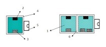
The sensor [8] is shown in Fig. 1 as a cable-cylindrical capacitor. Water molecules (4) freely pass through the outer shell (1) and drop into the sealing (3) made of capillary-porous material. An increase in the concentration of water molecules in the sealing leads to an increase of the electrical capacitance of the cable capacitor. Thus, an electrical signal is generated proportional to the change in humidity of the ambient air cable sensor.
An important advantage of our cable sensor is the fact that the entire cable surface serves as a sensor surface. Water molecules surrounding the cable (Fig. 2) are captured effectively. The area of this surface is ten thousand times larger than the comparable areas of sensory capture of any of the currently known point sensors.
A sensor cable can be represented as a combination of a plurality of measuring segments – as capacitors connected in parallel (Fig. 3). The overall capacity of such a system is defined as the sum of its constituent elements, according to the basic laws of electric circuits. Therefore, the measured signal of the sensor cable carries information about the average along the entire length of the cable.
Therefore, a cable humidity sensor can replace several (i.e. ten or more) conventional point sensors. It is no longer necessary to connect separate communication lines to each of these sensors. Moreover, there is no need to use a special processor in order to average the values of humidity received from them.
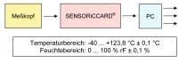
The CHS is both a measuring device and a communication line that is connected to a specific interface.
3 Measurement of the moisture of concrete using the cable sensor
Fig. 4 demonstrates the fundamental difference in terms of quality and volume of the information on moisture received from conventional point sensors and CHS. There are at least two types of trajectories for measuring moisture. For existing concrete components, it is determined by the directions of specially drilled holes in which the CHS should be inserted. In respect of newly manufactured concrete structures, there are practically no restrictions regarding the creation of any control path required by the customer. For this purpose, the measuring cable (Fig. 5) has to be attached to the reinforcement along the desired path, just before concrete pouring.
Attention should be paid to the fact that obtaining information on the kinetics of changes in the moisture content at an early stage of the concrete life cycle can be of crucial importance for taking decisions about when to remove the formwork.
This can result in actual cost savings of up to 20% of the total costs for concreting.
Fig. 6 shows the results obtained by experiments confirming this possibility by means of an M300 concrete block and three different CHS types „implanted“ during concrete pouring.
Such a technology for „implanting“ of CHS into concrete allows the creation of low-budget systems for online monitoring of humidity throughout the entire lifetime in virtually any concrete structure. For this purpose, it is sufficient to install only a section of the CHS when pouring concrete. Subsequently, this cable only needs to be connected on a regular basis so as to measure the actual average moisture level of the structure. The approximate operational life of such sensors is at least 50 years. Such solutions may be in demand, for example, for continuous monitoring of the moisture content of concrete used in moist soils.
In the course of the experiment, six different cable humidity sensors were implanted in an M300 concrete block in various distances to the water surface (Fig. 7). The passage of moisture into the interior of the product, being in permanent contact with water, was recorded reliably. The period for detecting the moisture front varied from 30 minutes to 6 hours, depending on the type of CHS and the distance from the front side of the water surface.
Fig. 8 shows the results of measuring the electrical resistance of the CHS implanted into the product when filling the mold with concrete (curing phase). After hardening of this product, water was poured into it; the diameter of the water spot was 5 cm. A certain time after the addition of water, the natural drying began. These experimental results confirm the actual sensitivity of the CHS to various technological phases and changes in external conditions.
4 Multi-zone humidity cable sensors
In order to expand the capacities of the CHS concept, the multi-zone humidity cable sensor was developed to localize measurements more precisely. The design of the multi-zone CHS provides for a separation of the cable in several zones which are functionally independent of each other (Fig. 9).
Each such zone generates a signal proportional to the average air humidity within this zone. In this way, the possibility of an independent multi-zone control of the distribution of humidity along a selected path inside concrete structures was realized with the aid of such a multi-zone CHS.
5 Application of humidity cable sensors
The simplest and most economical way to install CHS in concrete is to fix it to the steel reinforcement. In this case, the cable literally starts „working“ from the very first minute after pouring of concrete and generates an electrical signal that carries information about the changes in the content of free or bound water in the concrete.
In order to control the air humidity in existing concrete structures, it is necessary to pre-drill the fixing holes with a diameter of 5 to 8 mm in the correct direction and to fix the CHS therein by means of cement mortar. It should be noted that, in this case, the area of the hole is 10-15 times smaller than the cross section of the holes specified by the current standards. Such drillings can be classified as minimally invasive and virtually do not perforate the structural component. As soon as the CHS are connected to the concrete, they are completely ready for the moisture measuring process at any time, even after many years and decades.
In case of excessive humidity in the controlled section of Fig. 12, this system activates the radio channel and transmits an incident message to the central control point. One of the most promising fields of application here is the control of leakages in the so-called expansion joints as well as other joints. The layout of the CHS for such „cold“ joints is illustrated in Fig. 13.
Fig. 14 shows a full-size stand demonstrating options for the possible use of CHS for the comprehensive control of moisture and leakages in joints of reinforced concrete structures that are not easily accessible.
At the first signs of deviations in the hydraulic modes of the structures, the processor sends a signal accordingly, giving the user the exact coordinates of the place. Such early diagnosis allows the user to quickly take preventive action to eliminate any ingress of water and reduce corresponding damages.
The mentioned examples, of course, do not limit the potential range of applications of the CHS. These may be special structures operated under difficult operating conditions such as storage facilities for hazardous liquid waste, bridges, airport runways made of concrete, etc.
REFERENCES/LITERATUR