Precast wall units conforming to the new Guideline on Waterproof Concrete Structures (Part 2)
![Fig. 3: Waterproof concrete precast wall unit with bilateral horizontal distribution reinforcement (left) and double-layer vertical connecting reinforcement (right) in the cast-in-place infill portion and inside waterstop (taken from [3])](https://www.bft-international.com/imgs/1/4/6/8/8/5/5/HA_1012_Fig.3_Bild_3_links_und_rechts-d20ff71a1b6e72a2.jpeg)
![Fig. 4: Waterproof concrete precast wall unit with non-reinforced cast-in-place infill and inside waterstop (clearance between the insides of the precast wall unit) (taken from [3])](https://www.bft-international.com/imgs/1/4/6/8/8/5/5/HA_1012_Fig.4_Bild_4-c017a502d5b90cdb.jpeg)
![Fig. 5: Waterproof concrete precast wall unit with double-shear (left) and single-shear (right) connecting reinforcement in the cast-in-place infill portion with a minimum longitudinal rebar-to-rebar clearance of 100 mm and outside waterstop (taken from [3])](https://www.bft-international.com/imgs/1/4/6/8/8/5/5/HA_1012_Fig.5_Bild_5-4aa62814d11857d1.jpeg)
![Fig. 6: Possible routing of the concrete pumping hose in a precast waterproof wall unit; example with double-layer reinforcement (top) and single-layer reinforcement (bottom) [axial distances in mm]](https://www.bft-international.com/imgs/1/4/6/8/8/5/5/HA_1012_Fig.6_Bild_6_Moegliches_Fuehren_des_Betonierschlauchs-b8ad8309c1a64367.jpeg)


This article elaborates on the more sophisticated design and structural requirements for waterproof precast wall units contained in the new version of the Guideline on Waterproof Concrete Structures, which has been available since February 2018. In addition, it will report on initial experience gained in applying these new specifications. This second part of this article also includes specific examples from practice. Its first part was published in the July 2019 issue of BFT International, pp. 34.
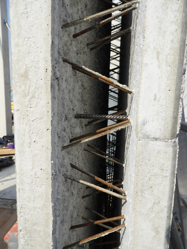
If supplementary reinforcement is installed as a vertical connecting reinforcement in the cast-in-place infill portion in combination with inside waterstops, care must be taken to avoid that the reinforcement and waterstops are positioned too close to each other, or even make contact. Only if a sufficiently large spacing between the waterstop and the vertical connecting reinforcement is ensured will cavity-free embedment of the waterstop in the concrete (i.e. a tight enclosure) be achieved in the base area. The clearance between the waterstop and the vertical connecting reinforcement should be at least 50 mm to all sides, similarly to the specifications for waterstops contained in DIN 18197 [9], Fig. 19. This value takes into account clearance variations between the waterstop and the vertical connecting reinforcement that inevitably occur during the installation process on the job site. If we assume, for instance, the height of the anchor ribs of the waterstop to be 20 mm, this results in a minimum internal clearance bw,i of 120 mm between the rebars of the vertical reinforcement (special requirements); see Case 1. If no supplementary reinforcement is installed in the cast-in-place portion in precast wall units with inside waterstops, the internal clearance dimensions bw,i apply to the cast-in-place infill between the precast wall panels (standard requirements); see Case 2.
To also ensure adequate compaction of the waterproof cast-in-place concrete (core mix) in the base area if outside waterstops are installed without supplementary reinforcement, the internal clearance dimensions bw,i between the precast wall units in accordance with [1], Section 7.2 (3) must be adhered to (standard requirements). In the case of supplementary reinforcement installed in both the vertical (connecting reinforcement) and the horizontal direction (distribution reinforcement) in the cast-in-place portion in combination with an outside waterstop, the internal clearance dimensions bw,i required between the reinforcement layers for ensuring appropriate concrete placement (i.e. insertion of the concrete pumping hose and vibrator) in accordance with [1], Section 7.2 (3) must be complied with (special requirements).
Case 3 discusses the situation where only a supplementary vertical reinforcement (connecting reinforcement) is installed in combination with an outside waterstop. For non-standardized waterstops, such as coated inside metal waterstops or outside strip seal systems, [1] requires usability, or fitness for use, certification, for instance by obtaining a general test certificate on the basis of testing principles published by Deutsches Institut für Bautechnik (DIBt). A list of currently issued general test certificates can be accessed at //www.abp-fugenabdichtungen.de" target="_blank" >www.abp-fugenabdichtungen.de:www.abp-fugenabdichtungen.de (among other sources).
Case 1: Double-layer vertical connecting reinforcement with or without horizontal distribution reinforcement in combination with an inside waterstop
At a maximum aggregate size of, say, 8 mm, an internal clearance between the two vertical reinforcement layers of bw,i ≥ 120 mm must be adhered to (special requirements); see Fig. 3, left and middle. We thus obtain, for a carefully inserted horizontal distribution reinforcement, a minimum cast-in-place infill thickness of 180 mm at an assumed rebar diameter of 10 mm whilst considering a minimum lateral concrete cover of 10 mm to ensure a firm bond. If the design includes horizontal distribution reinforcement, these parameters result in a total thickness of the precast waterproof concrete wall unit of at least 300 mm.
In the absence of horizontal distribution reinforcement, only the minimum cast-in-place infill thickness will be reduced from 180 mm to 160 mm, whereas the required internal clearance between the two vertical reinforcement layers remains unchanged (bw,i ≥ 120 mm). Likewise, the requirement of cavity-free embedment of the waterstops by ensuring a sufficient distance from the connecting reinforcement (special requirements) remains identical. These specifications result in a total precast wall panel thickness of at least 280 mm, but this value does not yet include dimensional variations that inevitably occur when inserting the double-wall units in the top-down direction via the connecting reinforcement.
Case 2: Inside or outside waterstop: no reinforcement in the cast-in-place infill portion
If the cast-in-place portion is designed completely without reinforcement (i.e. assuming a pinned joint at the wall base and verifying the precast waterproof wall panel as a non-reinforced concrete wall due to the absent anchoring of the vertical wall reinforcement), the internal clearance dimensions bw,i between the precast wall units in accordance with [1], Section 7.2 (3) must be adhered to (standard requirements). This applies both to inside (Fig. 4) and outside waterstops.
Case 3: Outside waterstop: single- or double-layer vertical connecting reinforcement, no horizontal distribution reinforcement
In precast wall panels without horizontal distribution reinforcement in the cast-in-place portion, concrete pumping hoses and vibrators can also be inserted in the longitudinal direction of the wall and routed between the vertical reinforcement layers if these ensure a(n internal) rebar clearance of at least 100 mm [3] see Fig. 6. In this case, for ensuring appropriate concrete placement, it is sufficient to consider the internal clearance bw,i in accordance with [1], Section 7.2 (3) between the precast wall panels (standard requirements); see Fig. 5.
To prevent unfavorable concrete pumping hose routing from great heights between connecting rebar layers, the connecting reinforcement should, as far as reasonably possible, be restricted to a height smaller than or equal to 1 m in the cast-in-place infill in order to limit the drop height of the concrete. If and when required, the hose can also be pulled over individual rebars (cf. Fig. 6, top) or be in contact with the inside surface of the precast panel (cf. Fig. 6, bottom). A connecting reinforcement rebar spacing (axial dimension) of about 100 mm in the longitudinal direction is sufficient for inserting the vibrator. Among other sources, DBV-Heft 43 [3] lists other typical installation layouts of precast waterproof wall panels.
In summary, we find that requiring minimum clearance dimensions bw,i may result in the total thickness of waterproof precast wall units exceeding the minimum thicknesses specified in Table 1; compare, for instance, Case 1 (Part 1 in BFT 07/2019 pp. 34).
Consequently, the common practice of switching from a waterproof cast-in-place wall with a minimum thickness of 240 mm to precast waterproof panels at the detailed design stage or even in the construction phase will no longer be an option in a large number of scenarios under the new Guideline on Waterproof Concrete Structures because this would require adjustment of the concrete mix (maximum aggregate size), reinforcement (connecting reinforcement, i.e. this will already be relevant for the foundation slab), and the thickness of the wall unit.
Connecting cast-in-place mix for precast waterproof wall units
Irrespective of the “special requirements for internal clearance dimensions bw,i“ depending on the maximum aggregate size ([1], 7.2 (3)), a connecting, or transitional, concrete mix with a maximum aggregate size of 8 mm must be placed for precast waterproof wall panels with a height of at least 300 mm if the concrete drop height exceeds 1 m or if the minimum thickness according to Table 1 (240 mm to 275 mm) or a minimum core mix thickness (120 mm to 140 mm) is fully utilized.
For precast waterproof wall units designed with minimum thicknesses according to Table 1, a waterproof concrete with (w/c)eq ≤ 0.55 (C30/37) and a maximum aggregate size smaller than or equal to 16 mm must be used in exposure class 1.
The principle of fully utilizing minimum thicknesses no longer applies if element thicknesses are at least 15% greater than the specified minimum values.
General guidance on connecting reinforcement in the foundation-wall construction joint in precast wall panels
The design of the foundation-wall construction joint almost always includes the installation of connecting reinforcement. In combination with horizontal distribution reinforcement, this type of reinforcement can render concrete placement more difficult (see above) or influence the internal clearance dimensions bw,i, and thus the total thickness of the precast wall unit. Furthermore, the connecting reinforcement projecting from the foundation makes the assembly and erection of precast wall panels more complex because the panels must be inserted in the connecting reinforcement projecting from the foundation with a high degree of care and precision while being lifted by a crane. Another obstacle is created by the lattice girders between the two precast panels, which often collide with the connecting reinforcement. This is why, in actual practice, the portion of the connecting reinforcement close to the lattice girders is often removed.
However, it is questionable whether connecting reinforcement is always necessary from a structural point of view. In many cases, such a reinforcement is included in the design because “this is just how it’s done.” From a practical standpoint, it would be desirable to not install connecting reinforcement if the structural design permits in order to simplify the installation process and to reduce the thickness of the wall (see above). The wall is then designed as a non-reinforced concrete wall, particularly because there is no anchoring of the vertical wall reinforcement. In such a design, the reinforcement installed in the precast wall units often only serves to ensure structural stability during transport and assembly. In this context, we also note that masonry walls, for instance, do not include reinforcement connecting to the foundation slab due to their system design.
General guidance on the reinforcement in the wall-wall butt joint
Butt joints of precast waterproof wall units are often strengthened by installing stirrup cages. In precast waterproof wall panels, design principle c) according to the Guideline, i.e. only a few wide cracks that are sealed in accordance with the design, is usually the most appropriate option. Design cracks occur in the butt joints structurally weakened by controlled crack joints; such cracks are sealed by appropriate seals as specified in the design. Installing horizontal reinforcement in the butt joint can limit the width of the design crack and ensure a fine distribution of smaller cracks. This means that additional (unsealed) cracks may occur besides the crack in the butt joint. Consequently, any non-structural butt joint reinforcement must be eliminated when applying design principle c).
Installation of waterproof precast wall units
Upon on-site acceptance of precast waterproof wall units, the roughness of the panels’ inside surfaces must be checked (see above). Also, as little cement slurry as possible should adhere to the inside wall surfaces.
Precast panels must also be inspected for damage, such as edge breakage or cracking. Damaged panels must not be installed or must be repaired prior to their installation.
Near the foundation-wall construction joint, precast wall panels must be elevated by at least 30 mm and positioned at the base in order to ensure cavity-free concrete flow underneath the wall units and thus enabling load transfer via the entire wall-foundation contact zone. The foundation-wall construction joint should be inspected after concrete pouring.
Foundation-wall construction joints must be cleaned prior to installing the precast wall units. Care must be taken to ensure that no resoiling of the joint occurs after assembly of the wall panels. However, this will not always be possible for practical reasons because the joint is usually only visible or accessible at a height of 30 mm immediately above the foundation slab. Furthermore, installed waterstops or connecting reinforcement can obstruct the visibility of soiling and/or make cleaning more difficult.
Concreting of waterproof precast wall units
The panels’ inside surfaces and the construction joint to the foundation slab must be sufficiently pre-wetted (to a slightly damp condition). Both the start and the end time of pre-wetting must be recorded (this is often forgotten!). Particular care is required under freezing conditions (water must not freeze on inside surfaces and at the base). Final formwork positioning in the foundation-wall joint should only occur after pre-wetting or completed water drainage.
Concrete must be poured evenly in horizontal layers with a maximum height of about 500 mm, ensuring that the mix rises uniformly across the entire concreting section. This particularly applies to the butt joint area in order to prevent displacement of the waterstop by unilateral concrete pressure. No horizontal construction joints should be created in the core mix of the wall, which means that the concrete should be placed and needled or compacted sufficiently quickly (ensure appropriate concreting speed!).
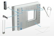
In larger blockouts in the precast wall panels, for example to accommodate windows, care must be taken to ensure that the concrete also fills the area underneath the blockouts and can be compacted in this zone, for instance by concrete chutes or compaction tubes.
Outlook
The 2006 edition of DAfStb-Heft 555 (Explanations on the Guideline on Waterproof Concrete Structures 2003 [2]) [10] is currently being revised and aligned with the new Guideline [1]. The revised version should also include initial practical experience in applying the new Guideline [1], as well as first responses to design issues. The revised edition of DAfStb-Heft 555 is scheduled for publication in 2020.