Precast wall units conforming to the new Guideline on Waterproof Concrete Structures – Initial experience
![Fig.2: Principle of the sand-area method [6]](https://www.bft-international.com/imgs/1/4/5/7/3/1/1/HA_1012_Fig.2_Bild_2_Prinzip_des_Sandflaechenverfahrens-a7fa4aff3e4a228e.jpeg)
This article elaborates on the more sophisticated design and structural requirements for waterproof precast wall units contained in the new version of the Guideline on Waterproof Concrete Structures, which has been available since February 2018. In addition, it will report on initial experience gained in applying these new specifications. This is the first part of this article; the second part with specific case studies will be published in the August 2019 issue of BFT International.
Introduction
The new Guideline on Waterproof Concrete Structures (December 2017 edition, [1]) has been available since February 2018. DBV Heft [Volume] 43 [3] contains a summary of the revised specifications included in the new version of the guideline. This article elaborates on the more sophisticated design and structural requirements for waterproof precast wall units contained in [1] ]. In addition, it will report on initial experience gained in applying these new specifications.
[1] generally specifies the following: “The insides of precast wall units and the top sides of precast floor slabs must be of a quality that ensures a firm bond and cavity-free connection between the core concrete layer and the precast wall element, or between the concrete topping and the precast floor slab, resulting in a precast component with a monolithic appearance that prevents water ingress between cast-in-place concrete and semi-precast elements.”
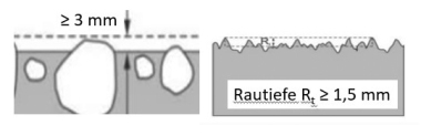
The more sophisticated requirements for waterproof precast wall units include the specification of a “rough grain texture of the complete bond surface” (inside surface of the wall element) and the corresponding increase in the so-called mean surface roughness of the inside surfaces of precast wall panels from 0.9 mm [2] to 1.5 mm [1], which also applies to waterproof precast floor slabs.
[1] contains several other new additions, including specific requirements for clearance dimensions (i.e. the minimum thickness of the cast-in-place layer or, under certain conditions, the spacing of reinforcement layers within the cast-in-place infill portion – supplementary reinforcement). This results in the following two possibilities:
the minimum thickness of precast waterproof wall units produced according to the new guideline [1] can exceed the previously applied standard minimum thickness of precast waterproof wall units produced according to [2] or
the minimum thickness of precast waterproof wall units produced according to the new guideline [1] can exceed the minimum thickness of cast-in-place walls.
Requirement of a “rough grain texture of the complete bond surface“ and increase of the so-called mean surface roughness to 1.5 mm
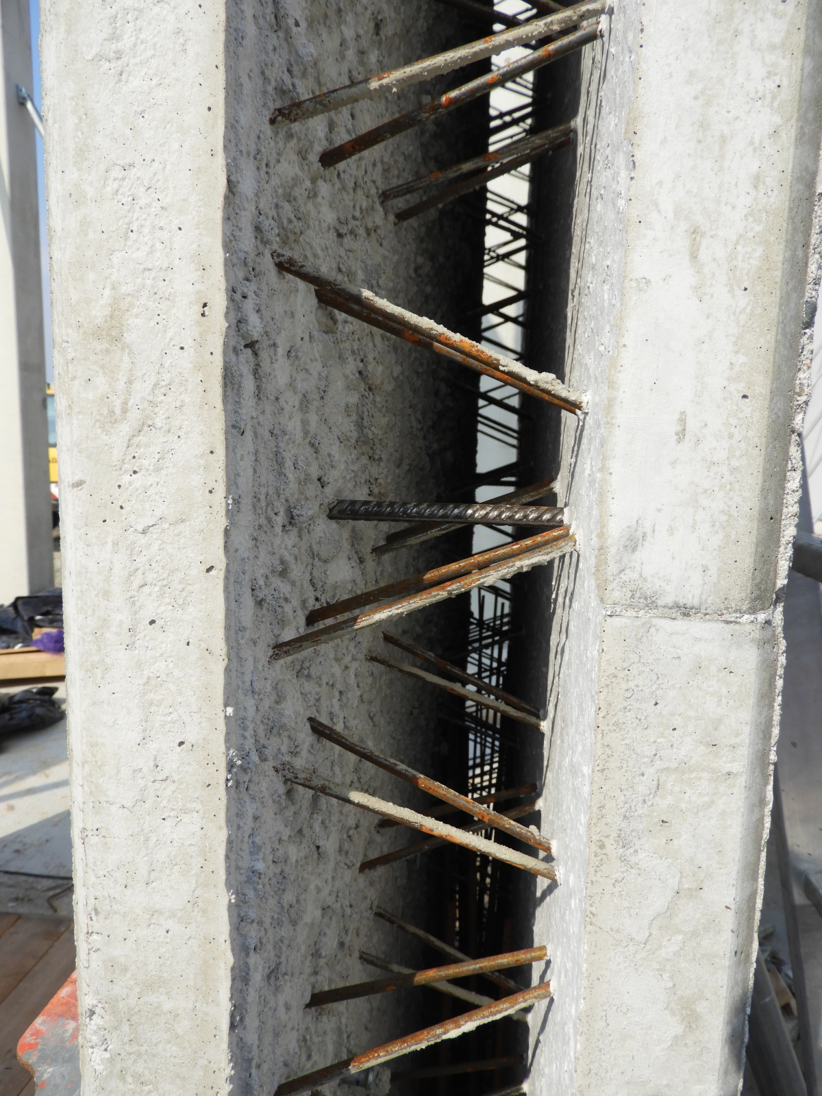
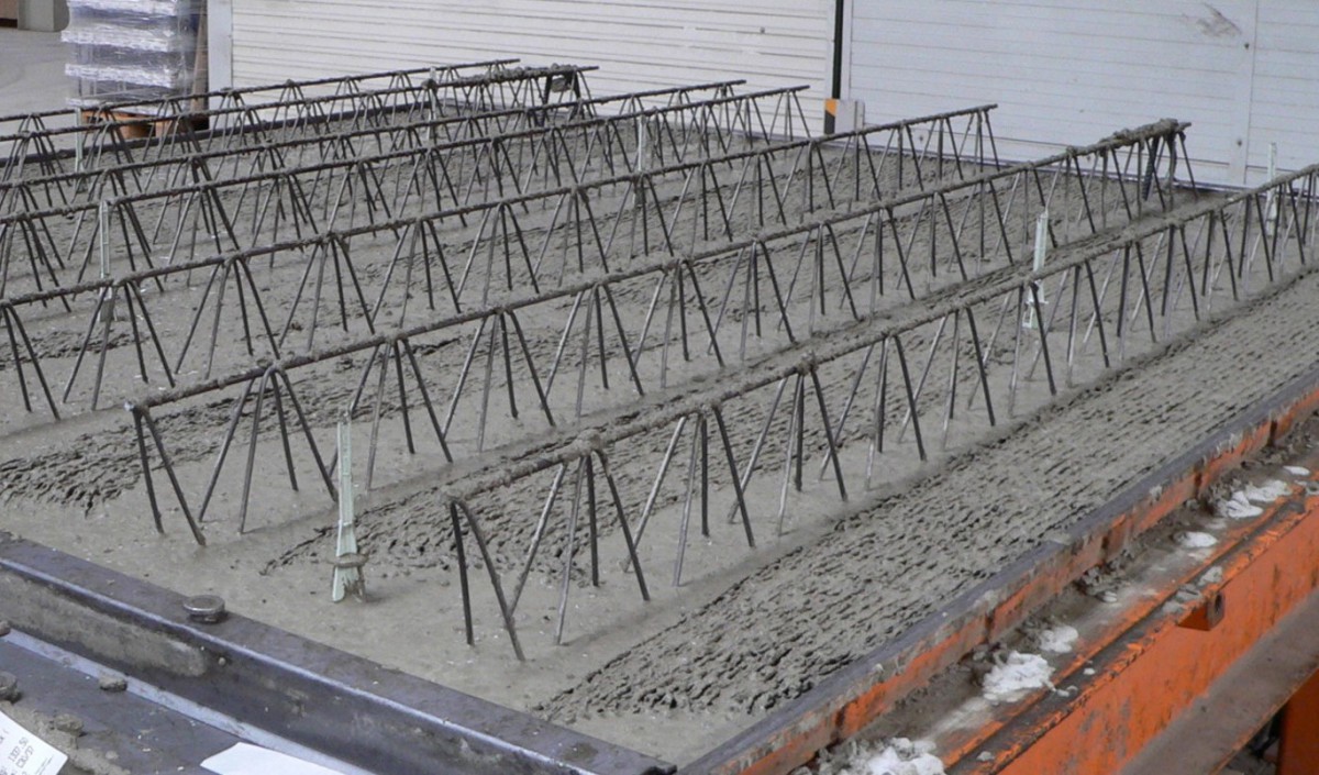
In precast waterproof wall units, a rough grain texture of the complete bond surface can be achieved only by appropriate concrete technology adjustments, such as the concrete mix design (aggregates), workability, and a minutely controlled vibration process resulting in a so-called “vibration-roughed” surface. Due to the production setup, the inside surface of the second precast panel usually has a slightly lower roughness (see Fig. 1a). Both inside surfaces of the precast wall unit must exhibit a so-called mean surface roughness of 1.5 mm across the entire surface. Manual roughening using a rake, for instance, is not appropriate for precast waterproof wall units and floor slabs because the concrete surfaces located near the lattice girders are very difficult, if not impossible, to reach when applying such methods (see Fig. 1b).
In this context, the reference to the complete surface means that smooth areas underneath the lattice girders must not be “compensated” by roughened areas located in-between. This requirement appears plausible because so-called “water roads” in the lattice girder zone should be avoided.
[1] specifies that the so-called mean surface roughness Rt must be verified on the inside surfaces of the two precast wall panels or on the surfaces of precast floor slabs after concrete hardening, while closely following the provisions of Section 7.2 of DIN EN 1766:2000-03 [4] applying the sand-area method according to Kaufmann [5]. Fig. 2 illustrates the basic principle of this method.
[4] requires the surface to be subjected to testing to be clean and dry. The diameter d of the sand area resulting from the circular distribution of a given sand volume V must be measured at three points equally distributed across the sand area, and the mean value of d must be calculated with millimeter precision. Equation (1) must then be applied to calculate the surface roughness expressed in millimeters.
Surface roughness = 4 × V/(π × d²) =
V [ml]/d [mm]² × 1272 (1)
With regard to Equation (1), it should be noted that the concepts of “mean surface roughness” and “surface roughness” are generally taken to be synonyms. DIN EN 1766:2000-03 [4], for instance, only uses “roughness”, unlike the Guideline on Waterproof Concrete Structures. This interpretation also becomes apparent when looking more closely at the wording of the DAfStb Repair Guideline [7] and the ZTV-ING [8].
The DAfStb Repair Guideline, Section 3.2.5, says:
“The mean surface roughness Rt is defined as the height of the notional cylinder with the diameter d and the sand volume V. […] Applying the sand volume V (cm³) and the diameter d (cm) of the approximately circular sand area, we obtain the mean surface roughness Rt (mm) as Rt = 40 × V / (π × d²).“
Compare this to the wording of ZTV-ING, Part 1-3, Section 4:
“Surface roughness is defined as the height of the notional cylindrical body with the circle diameter and the sand volume. […] Applying the sand volume V (cm³) and the diameter d (cm) of the approximately circular sand area, we obtain the surface roughness Rt (mm) as Rt = 40 × V / (π × d²).“
Form B 1.3.3 of Part 1-3 of the ZTV-ING [8] refers to a mean value calculated from three individual values of the surface roughness Rt as the “mean surface roughness Rtm”, while making an explicit distinction between the “t” and “tm” indices. Calculating the “mean surface roughness Rtm” refers to Item B 1 in Part 7-1 of the ZTV-ING, which specifies that, in the construction phase, a test comprising three individual measurements according to Part 1-3 must be performed per each 500 m² of applied bridge pavements, and the “mean surface roughness Rtm” must be determined as a criterion for treating the concrete surface in accordance with Part 7-1, Section 5.5.3. In the context of applying the Guideline on Waterproof Concrete Structures, this means that the requirement of a (mean) surface roughness Rt of at least 1.5 mm must be complied with separately for each sand area. This specification is supported by simultaneously requiring a “rough grain texture of the complete bond surface”. The Guideline on Waterproof Concrete Structures [1] does not specify a “mean surface roughness” to be determined by averaging on the basis of several sand areas (measuring points) in the case of uneven concrete surfaces. Any such specification would contradict the general approach followed in the guideline.
Thus, the specified increased (mean) roughness of the bond surface automatically requires a more stringent quality control system at the precast plant, primarily with regard to testing as part of in-process quality control and its documentation.
The above requirements result in the following process sequence for construction sites:
Order precast wall units explicitly in accordance with the new Guideline on Waterproof Concrete Structures, December 2017 edition [1],
Recommendation: As part of the order, request documentation of the visual inspection performed at the precast plant
Perform random visual inspections of precast wall units upon delivery (e.g. in comparison to a reference element), carry out measurements if and when required.
Random visual inspections on the construction site make it possible to ascertain if the concrete exhibits a relatively even surface texture. Based on some degree of prior experience, precast waterproof wall units with suspected non-conformance with the specified (mean) surface roughness can be identified. In such a case, surface roughness measurements must be performed on-site using the sand-area method or, if and when required, laser-based methods.
Requirements for clearance dimensions bw,iin waterproof precast wall units
Section 7, Table 1 of the new Guideline on Waterproof Concrete Structures [1] contains recommended minimum thicknesses for precast waterproof concrete elements depending on their exposure class, type of component, and design (see Table 1).
The minimum thicknesses recommended in Table 1 are based on many years of experience. These minimum thicknesses were introduced to prevent capillary migration through the precast waterproof element (cf. also [555]) and to enable effortless concrete pouring across the entire cross-section with the aim of ensuring the “bearing and sealing function” of the element (cf. [1], 7.2 (1).
The recommended minimum total thicknesses of precast waterproof wall units and cast-in-place walls are identical for exposure class 1 (pressing water) (Table 1, Line 1). In exposure class 2 (moist earth), permissible thicknesses of cast-in-place walls are smaller than those of precast waterproof wall units (Table 1, Line 2).
Besides recommended minimum total thicknesses for precast waterproof wall units, Table 1 also includes minimum thicknesses for the cast-in-place infill portion. Irrespective of exposure classes, this minimum amounts to 120 mm for precast waterproof wall units (Table 1, Lines 1 and 2, Column 4, values in parentheses, or Table 1, Footnote b), first sentence). The minimum thickness of 120 mm specified for cast-in-place infill portions of precast waterproof wall units was taken from the previous edition of the Guideline on Waterproof Concrete Structures [2].
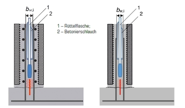
[1], Section 7.2 (3) also includes requirements for the clearance dimensions bw,i between the inside surfaces of precast walls for ensuring effortless concrete pouring and appropriate installation of inside waterstops. These dimensions must generally be adhered to for exposure class 1 (pressing water). In the following paragraphs, the requirements for the clearance dimensions bw,i between the inside surfaces of precast walls are referred to as “standard requirements”.
If the cast-in-place portion includes an inside waterstop and supplementary reinforcement (cf. third sentence in [1], Table 1, Footnote b)), [1], 7.2 (3) specifies that the clearance dimensions bw,i must generally be measured between the reinforcement layers embedded in the cast-in-place concrete. In the following paragraphs, the requirements for the clearance dimensions bw,i between the reinforcement layers are referred to as “special requirements”.
In precast wall units, the actual wall reinforcement is usually installed in the precast panel. Within the meaning of the Guideline on Waterproof Concrete Structures, the concept of “supplementary reinforcement” includes all reinforcement layers located in the cast-in-place portion of the element (core layer), i.e. a vertical connecting reinforcement and, in some cases, an additionally inserted horizontal reinforcement for load distribution purposes (cf. Fig. 3). If and when required, stirrups or reinforcing mesh with a horizontal component will also be installed in the butt joint area of the wall panels. Such reinforcement also falls under the “supplementary reinforcement” category in accordance with the Guideline on Waterproof Concrete Structures.
[1], Section 7.2 (3) specifies the values for the clearance dimensions bw,i depending on the maximum aggregate size (Dmax), as follows:
Dmax = 8 mm: bw,i ≥ 120 mm,
Dmax = 16 mm: bw,i ≥ 140 mm,
Dmax = 32 mm: bw,i ≥ 180 mm.
Specified bw,i values (special requirements) apply only to exposure class 1 (pressing water) in accordance with [1], Section 7.2 (3).
The special requirements for the clearance dimensions (bw,i between the reinforcement layers) should ensure appropriate concrete pouring in the core cross-section, i.e. effortless insertion of the concrete pumping hose, for instance to a maximum height of 1 m, and of the vibrator down to the base area. Supplementary reinforcement installed in the cast-in-place portion makes insertion of the hose and vibrator more difficult. To ensure either cavity-free embedment of inside waterstops (e.g. metal strips) or sufficient compaction of cast-in-place concrete in the base area, the requirements for the clearance dimensions bw,i generally distinguish between
inside waterstops and
outside waterstops.
Irrespective of the location of waterstops, care must be taken to ensure that the waterproof cast-in-place concrete (core mix) is always sufficiently compacted and protected against water ingress across the entire height of the wall exposed to pressing water.
Read Part 2 of this article in the August 2019 issue of BFT International.