Design of prestressed precast elements
in accordance with Eurocode 2
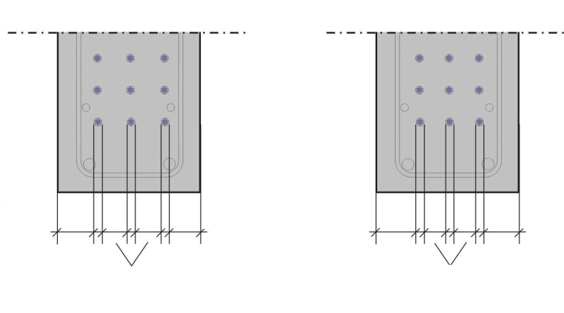 Figure: FDB
![2Dependencies on the degree of prestressing: (a) cost ratios for various prestressed precast elements (according to [7]), (b) losses of prestress due to creep and shrinkage (according to [9]), (c) required reinforcement As + Ap (excluding transverse or minimum reinforcement) (according to [9])](https://www.bft-international.com/imgs/103962485_343860ee69.jpg) Figure: FDB
Figure: FDB
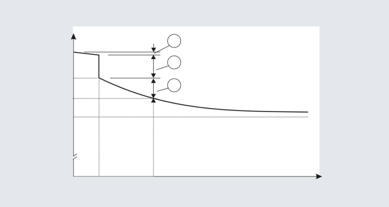 Figure: FDB
![4Graphical determination of modulus of creep at a relative humidity of 50% (taken from [4])](https://www.bft-international.com/imgs/103962498_7daafefe6a.jpg) Figure: FDB
Figure: FDB
![5Decompression verification: (a) with fully compressed cross-section; (b) using the decompression limit (taken from [4])](https://www.bft-international.com/imgs/103962510_89725fd396.jpg) Figure: FDB
Figure: FDB
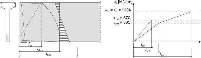 Figure: FDB
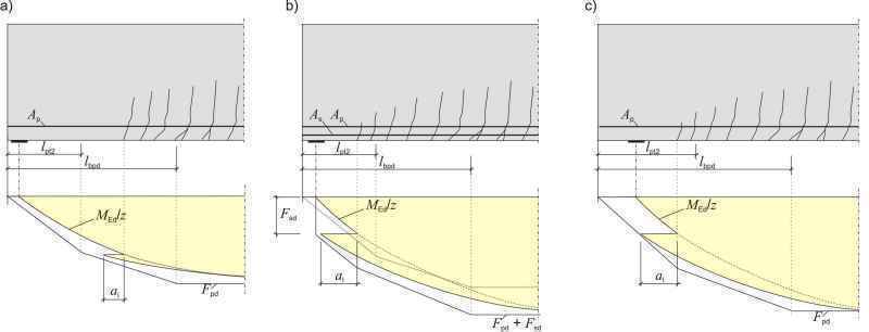 Figure: FDB
![8Structural system and lifting point for lifting the girder (taken from [4])](https://www.bft-international.com/imgs/103962487_b58fff95ec.jpg) Figure: FDB
Figure: FDB
![9Actions in construction condition (taken from [4])](https://www.bft-international.com/imgs/103962526_7bc5dee75a.jpg) Figure: FDB
Figure: FDB
![Tab. 1Limitation of stresses in accordance with EC2 (taken from [4])](https://www.bft-international.com/imgs/103962479_6ea1888848.jpg) Figure: FDB
Figure: FDB

From 2014, structural frameworks of buildings must be designed in accordance with EC2, with only a few exceptions. This article deals with the design of prestressed precast elements with pretensioned tendons.
1. Introduction
Upon the official introduction of Eurocode 2 (DIN EN 1992-1-1 [1], hereinafter referred to as EC2), several German states, including Bavaria, Hesse and North-Rhine Westphalia, provided the option, in mid-2012, to continue to design structural elements in accordance with withdrawn national standards (such as DIN 1045-1 [2]) until the end of 2013. From 2014, however, structural frameworks of buildings must be exclusively designed in accordance with EC2, with only a few exceptions. Since the middle of 2013, bridges have had to be designed in accordance with [3].
This article deals with the design of prestressed precast elements with pretensioned tendons according to EC2. Some of the images and calculations included in this article were taken from the worked example of “Prestressed concrete girders according to Eurocode 2” published by the Fachvereinigung Deutscher Betonfertigteilbau e. V. [4].
2. Concrete cover
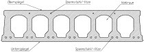
For prestressed tendons, EC2, 4.4.1.2 (3) specifies a minimum concrete cover of cmin,b = 2.5 Øp (where Øp is the tendon diameter) for fully utilized pretensioned strands whilst ensuring a minimum clearance between tendons of s ≥ 2.5 Øp (Fig. 1a). If the minimum clearance is lower (2 Øp), the minimum concrete cover should be increased accordingly to cmin,b = 3 Øp (Fig. 1b) [5]. According to [6], lower concrete covers may be sufficient under certain conditions.
3. Degree of prestressing
Depending on the relevant exposure class, the following minimum requirements exist for the degree of prestressing κ (i.e. the ratio of concrete stresses resulting from prestressing and concrete stresses caused by external actions) and thus for the prestressing force according to EC2, 7.3.1:
For X0 and XC1: the degree of prestressing may be freely selected ensuring a maximum crack width of wmax = 0.2 mm for a frequently occurring combination of actions;
For XC2 to XC4: decompression must be verified for a quasi-permanent combination of actions;
For XD and XS: decompression must be verified for a frequently occurring combination of actions.
The prestressing steel stress (prestressing bed stress σp,max) is defined whilst considering the verifications of stresses and deformation and the intended use of the element. For interior elements (XC1), the maximum prestressing steel stress is σp,max ~ 1,000 MN/m², whereas it amounts to σp,max ~ 1,100 MN/m² for elements in exposure clas-ses XC2 to XC4. Although EC2 permits the utilization of even higher prestressing steel stresses, these do not necessarily lead to optimum results in terms of serviceability and cost efficiency.
According to [7], the most economical range for the degree of prestressing of a T girder is κ = 0.3 to 0.7 (Fig. 2a). Reference [4] specifies a degree of prestressing of κ = 0.7 and a prestressing steel stress of σp,max = 1,000 MN/m² to provide a limitation of deformation and a sufficient safety margin against tilting.
Due to its clarity, the freely selectable degree of prestressing continues to be frequently referred to as “partial” prestressing, although this term taken from [8] is no longer used in the EC2. However, the benefits of partial prestressing remain the same:
The degree of prestressing and the prestressing force may be freely selected in response to the specific requirements.
Lower losses of prestress due to creep as a result of lower compressive stresses in the concrete (Fig. 2b);
Optimized reinforcing and prestressing steel quantities (Fig. 2c).
4. Losses of prestress
Immediate losses of prestress reduce the maximum prestressing steel stress σp,max and the maximum prestressing force Pmax to σpm0 and Pm0, respectively (prestressing steel stress or prestressing force at the time t = t0 after transmission of the prestressing force). EC2, 5.10.4 specifies the following immediate losses of prestress to be considered for determining Pm0 (Fig. 3):
Friction losses at deviators (usually non-existent when using pretensioned tendons);
The wedge slip in the strand anchorages is considered in the calculation of the expansion distance; it is accounted for in the prestressing instructions by an increase in the expansion distance.
Losses due to the short-term relaxation of strands should be taken from the national technical approvals granted to prestressing steel strands.
Losses of prestress resulting from elastic compression of the girder are determined on the basis of the identical strain of the concrete and the prestressing steel.
Time-dependent losses of prestress Δσp,c+s+r due to creep, shrinkage and long-term relaxation of the prestressing steel must be considered in accordance with EC2, 5.10.6. Unfavorable assumptions are made in this regard because the actual conditions for determining time-dependent losses of prestress are difficult to estimate. The most unfavorable case for determining losses of prestress due to creep occurs if the precast elements are put to storage for an extended period prior to their installation because their prestressing initially causes high, creep-inducing compressive stresses to act on the concrete, which is still at a relatively early strength stage. However, EC2 no longer includes the exceedingly conservative assumption according to [8], which specifies a storage period of six months, because precast elements are nowadays installed and subjected to loads at a much earlier point in time. Reference [4] thus assumes that the covering is added as early as after 21 days.
Losses of prestress due to creep and shrinkage will increase with decreasing humidity, which is why [4] specifies a safe constant humidity of 50% (alternatively, 70% in storage and installation condition and 50% in the final condition).
The shrinkage values, and thus the losses of prestress due to shrinkage, specified in the EC 2 are lower than those listed in the DIN 1045-1 standard. As a result, the capacity of prestressed precast elements can be utilized to a somewhat higher degree than according to DIN 1045-1. Modulus of creep values for concrete strength classes greater than or equal to C30/37 (and thus generally for precast elements) are identical to the values stated in DIN 1045-1. Modulus of creep may be determined graphically in accordance with EC2, 3.1.4 (Fig. 4).
Annex B to EC2 contains the basic equations to determine modulus of creep and dry shrinkage strain. These equations can be used to directly calculate the creep and shrinkage coefficients for various parameters (including varying humidities in storage and final condition). The sophisticated calculation outlined in [4] is associated with only minor benefits.
At concrete compressive stresses of σc > 0.45 fck(t0) (where t0 is the time of load application), EC2, 3.1.4 (4) specifies that the non-linear nature of creep should be considered by applying a larger coefficient of creep. However, the stress limit of 0.45 fck(t0) does not relate to short-term loading at the construction stage but to the permanent, creep-inducing load [5].
5. Decompression
For exposure classes XC2 to XC4 (such as open industrial buildings), decompression must be verified for the quasi-permanent combination of actions. This verification is not required for enclosed industrial buildings (exposure classes X0 to XC1).
Decompression can be verified either by a simplified method assuming a fully compressed cross-section (“full” prestressing, Fig. 5a) or on the basis of the decompression limit (similar to “restricted” prestressing according to [8], Fig. 5b).
The verification requirements according to [4] (Fig. 5b) are not met (σc,Dek = 0.8 MN/m² > 0) because the example relates to an interior structural component. The prestressing force would have to be increased or a larger number of strands be used if the component belonged in an exposure class greater or equal to XC2. The choice of the appropriate exposure class (open vs. enclosed building) is crucial because this consideration has a significant influence on cost.
Decompression need not be verified for the end section of a prestressed component. In the case of prestressing with pretensioned tendons, the length of this end section corresponds to the dispersion length ldisp in accordance with EC2, 8.10.2.2 (4). The serviceability of the end section is proven by verifying crack control (see also [5]).
6. Stress limitation
The stress verifications for concrete, reinforcing and prestressing steel are shown in Table 1. Mean prestressing forces may be used for the purpose of verifying stresses [5].
Furthermore, if pretensioned tendons are used, concrete compressive stresses that occur due to prestressing and own weight must be limited to σc ≤ 0.7 fck(t) at the time of transmitting the prestress in accordance with EC2, 5.10.2.2 (5). However, the utilization of the greater value of 0.7 fck(t) requires certain measures to be taken immediately after transmission of the prestressing force (i.e. checks for cracking within the transmission length) (see [5]). In all other cases, concrete compressive stresses (such as those occurring if post-tensioned tendons are used) must be limited to ´σc ≤ 0.6 fck(t).
If these requirements are not met in the bearing zone, one of the alternative options available is to apply a bituminous coating to some of the strands in order to insulate them. This insulation eliminates the bond effect in these areas so that the prestressing force is reduced in the bearing zone.
According to the DIN Technical Report 159, 4.2.3.2.3 [10], the concrete strength fcm,min(t0) must at least be equal to 1.5 times the maximum concrete compressive stress at the time of transmitting the prestressing force whilst amounting to at least 25 N/mm².
7. Transmission and anchorage of prestress
According to EC2, 8.10.2, the following distinctions must be made (Fig. 6):
Transmission length lpt: The prestressing steel stress at the end of the component is ´σp = 0 if pretensioned tendons are used. When making the simplified assumption of a constant stress curve, the entire prestressing force will have been transferred to the concrete at the end of the transmission length lpt. The design value for the transmission length is one of the values lpt1 or lpt2, whichever is more unfavorable.
Dispersion length ldisp: The strains across the concrete cross-section are non-linear until the end of the dispersion length ldisp has been reached (area of discontinuity). Only after this point does the curve become linear.
Anchorage length lbpd: The anchorage length is determined as σpd = fpd = 1,500/1.15 = 1,304 MN/m² in the ultimate limit state and thus reaches a higher design level. For this reason, a greater length is required to anchor the entire prestressing force in the concrete.
Within the transmission length, additional lateral compressive forces act perpendicular to the prestressing steel surface (Hoyer effect), which lead to an increase in bond stresses. This effect is not observed within the anchorage length. The design value for bond stresses within the anchorage length (value in [4]: fbpd = 1.9 MN/m²) thus corresponds to only half the value of the bond stresses within the transmission length (value in [4]: fbpt = 3.9 N/mm²).
The following cases are distinguished for anchorage verification purposes:
No cracking within the anchorage length lbpd: no further verifications of anchorage and no additional reinforcing steel are necessary.
Cracking within the anchorage length lbpd and outside the transmission length lpt2: no further verifications of anchorage are necessary, but additional reinforcing steel might be required to absorb tensile forces (Fig. 7a).
Cracking within the transmission length lpt2: either additional reinforcing steel (Fig. 7b) or a sufficient tendon overlap (Fig. 7c) is necessary. Alternatively, the prestressing force may be increased.
In general, those areas are considered cracked where the flexural stresses caused by external loads acting on the lower edge are greater than the concrete strength fctk,0.05 in the ultimate limit state whilst taking the prestressing force into account. Anchorage verifications differ only insignificantly from those outlined in [8].
8. Transport and assembly
When designing precast elements, EC2, 10.2 requires that temporary design situations be considered. For the purpose of bending and axial force design, the partial safety factors according to EC2, 10.2 (NA.4) may be reduced to γG = γQ = 1.15 for the transport and assembly conditions. Reference [4] assesses the following structural situations:
Lifting from the formwork and on the construction site, including the design of the transport anchor,
Transport to the construction site,
Assembly condition.
When lifting precast elements, it is crucial that the center of gravity of the element is located below the lifting points to ensure stability (Fig. 8). In this respect, it is important to also consider that the height of the lifting points varies as a result of using various types of transport anchors (for ball-head anchors, for instance, the height of the lifting point corresponds to the bottom edge of the anchor head). Reference [11] contains guidance for the design of transport anchor systems [11].
Furthermore, stability against tilting must be verified in the assembly condition in accordance with EC2, 5.9. The analysis of stability against tilting for the transport and assembly conditions depends on the time of lifting the element from the formwork and of its transport. This calculation uses reduced concrete strengths. The greater the distance of the lifting point from the beam end, the greater its stability against tilting, but the cantilever moment increases to the same extent.
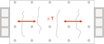
The inclination of the truck during transport is considered in [4] in a simplified manner applying a horizontal moment (Mz = 20% of My) and a dynamic coefficient of ´φ = 1.3 (see also [12]). During construction, the wind load may be reduced to 60% in accor-dance with DIN EN 1991-1-4, NA.B.5 [13] (Fig. 9) if no additional precautions are taken.
9. Summary
This article outlined several distinctive parameters that need to be considered when designing prestressed precast elements with pretensioned tendons in accordance with Eurocode 2 [1]. On the other hand, no radically new approach is required because many of the verifications are already known from the DIN 1045-1 [2] standard. Major industry associations have prepared worked examples (see [4] and [14]) to provide guidance to get familiar with the design of prestressed concrete elements on the basis of the Eurocode.