Spacers made of glass-fiber-reinforced plastics minimize thermal bridging in double walls
Core-insulated double walls manufactured with high efficiency and high quality are widely used worldwide. There is an increasing trend toward building with the least possible thermal conductance and with optimization of the insulation characteristics in walls.
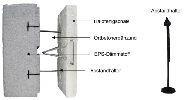
Composite anchors with glass-fiber-reinforced plastics (GRP) and with virtually no thermal conductivity are capable of eliminating numerous possible thermal bridges. In addition, spacers are frequently used to ensure dimensional uniformity of wall thickness. Suitable here are also spacers made of GRP, which are capable of eliminating additional thermal bridges
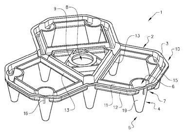
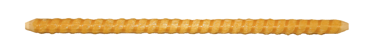
The GRP spacer developed by B.T. innovation GmbH features wound surface profiling, which ensures optimized keying with the concrete. The support surface is partially sharpened to keep it as small as possible to ensure that the bars are inconspicuous in the completed wall and to achieve optimal visual appearance. They still provide sufficient stability for minimizing shifting of the first shell toward the second shell during production.
Tested for use in precast plants
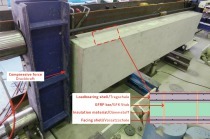
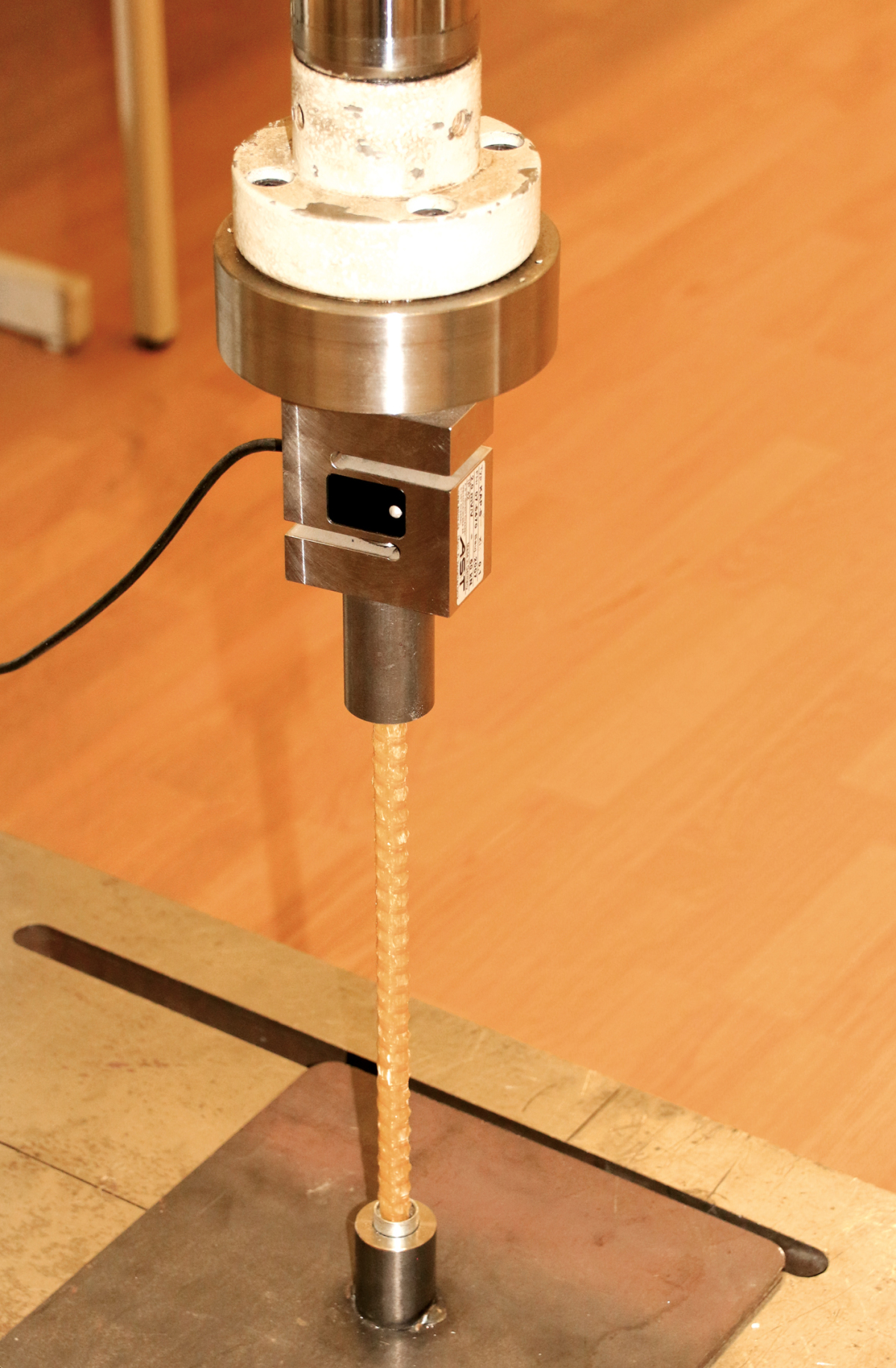
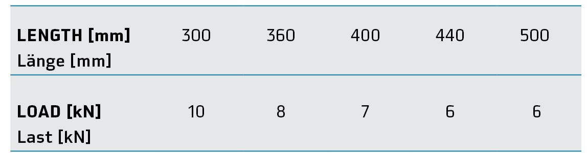
For use in precast plants, the sustainable load is the required characteristic value. To determine this load, ten bars – each as long as the GRP spacers specifically manufactured for this purpose – were individually and consecutively fixed in a test press and tested for the tolerable compressive load. For this process, each bar was fixed in two sleeves and subjected under continuous jacking of 20 mm/m to a pressure of 6 metric t. Two failure criteria were defined: for bending and compressive strain. Once the bars began to buckle or to compress at the support surfaces, they can no longer ensure maintenance of the desired distance. For every measurement, the value attained at the onset of criterion failure was recorded. The highest and the lowest measured values were discarded, and the characteristic load was determined based on the average determined from the remaining eight values, which were rounded to the next-smaller natural figure. Bars of 300 mm, 360 mm, 400 mm, 440 mm, and 500 mm length were used for this test series.
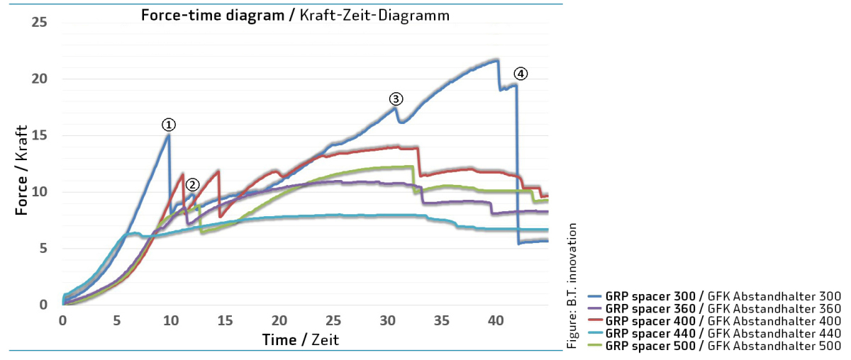
The GRP spacer of 300 mm length, as expected, showed the highest loadbearing capacity. Deflection of the bar became evident only under very high loads, considerably above 10 kN. The failure criterion in this measurement series was determined to be the point at which compression of the glass-fiber-reinforced plastics occurred under an imposed load of 15 kN – which becomes evident by marked decrease in the measured force (Fig. 2; 1.). Under increasing load, at around 10 kN (Fig 2.2), the second support area fails as well. The low load value, compared to the failure value of the first point of support, is attributed to the already damaged support area, where impairment occurred during initial increased loading. Under continuous loading, interlaminar shear failure (Figs. 2, 3.) then occurred, leading to fracture of the glass fibers (Figs. 2, 4.).
Various experiments performed
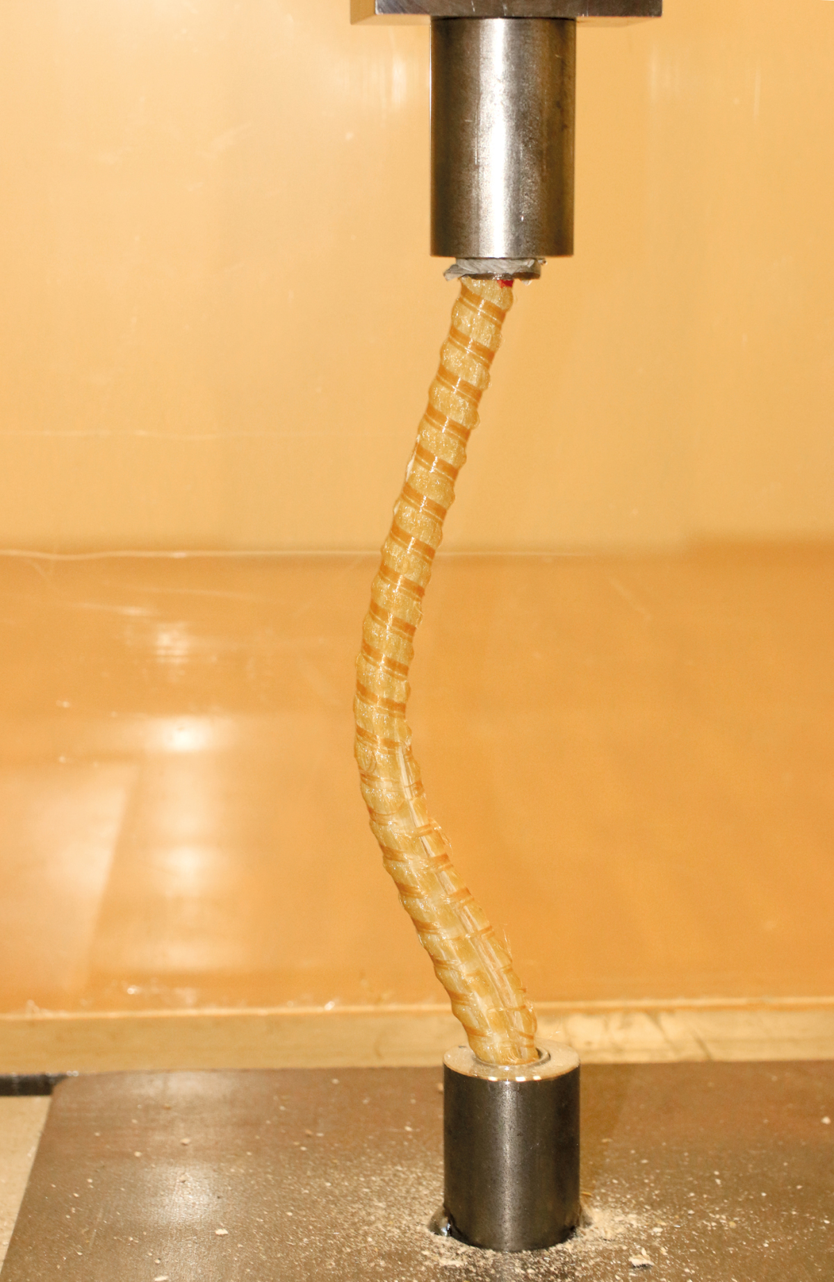
The plot of the measurement curves for GRP 360 spacer is similar to the measurement plots of bar 300, except that with 360 the loads imposed affect the bar negatively at an earlier point of time. In addition, deflection already occurs under an average load of 8 kN. The plots of the measurements become increasingly flatter as the bar lengths increase from 400 to 500 mm. Failure of the glass fibers at the support points becomes less dominant, and deflection begins only markedly later. A jagged plot with sudden failure at the support points virtually becomes no longer evident. Deflection up to interlaminar shear failure or fracture of the glass fibers is observed under increasing load.
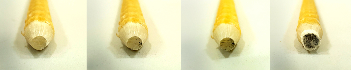
In an additional experiment, a very short bar was subjected to successive compressive loading, increased in each step by 1 kN: beginning with 1 kN to 11 kN and with loading in every stage sustained for 5 minutes. This process determined the point at which compressive loading began to cause the ends to fray (Fig. 3). The edges of the first fibers began to fray minimally at 4 kN. This condition remained stable up to a load of 10 kN; beginning with 11 kN, partially sharpened ends compressed with audible cracking. Since all the GRP spacers longer than 360 mm began to deflect prior to that point, buckling of the bars is a less significant failure criterion.
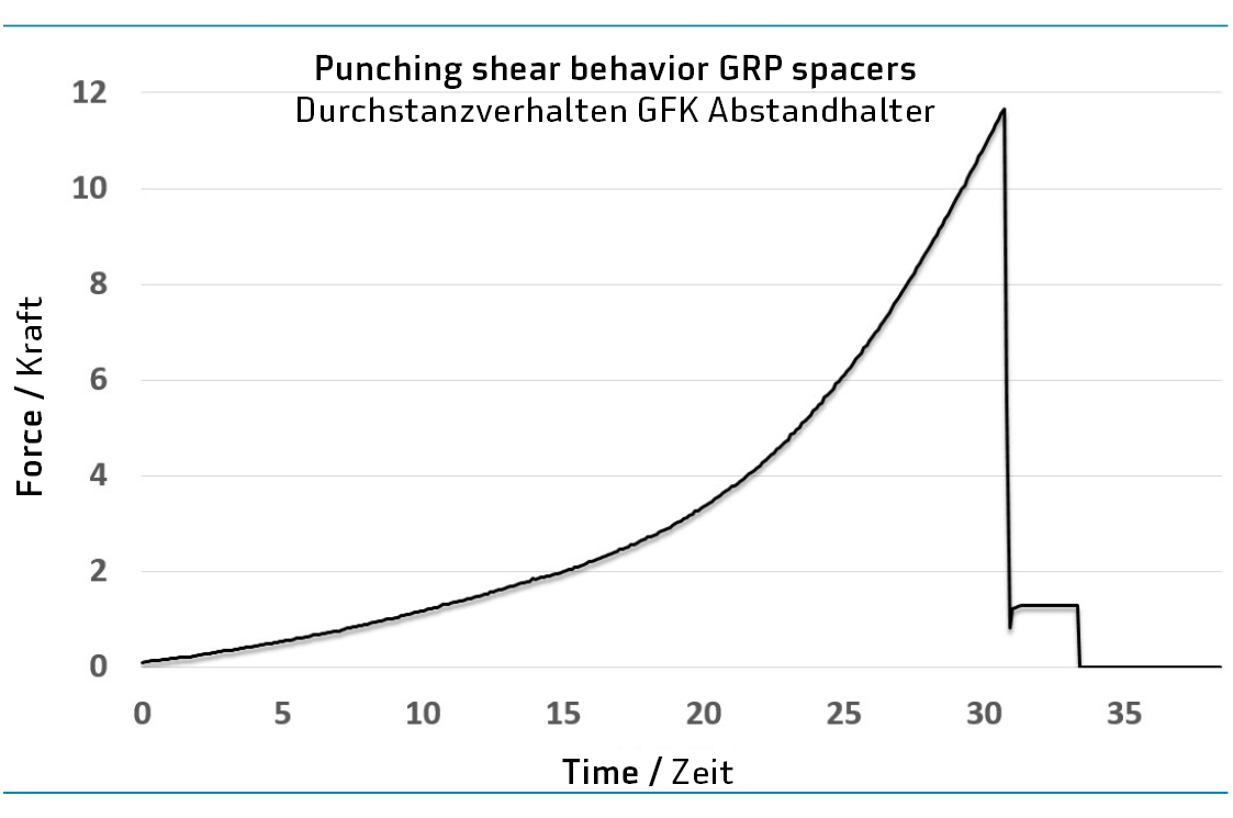
Finally, the punching shear behavior of the bar was investigated. For this purpose, one half of a GRP spacer was embedded in concrete 7 cm thick with strength class C30/37. Upon attainment of the final strength of the concrete, the bars were pressed through the concrete by the testing press.
In every case, the form of the bar was not negatively affected and was pressed through the concrete at an average value of approx. 12 kN. This value is lower than the tolerated load value shown in Table 1 and therefore does not represent a dominant failure criteria in service. A wall constructed with a shell thickness of 7 cm demonstrates at a density of 2.5 t/m³ a weight force of 1.7 kN per approx. 1.7 kN/m², so that use of a GRP spacer with one bar per square meter is on the safe side in any case.