Compressive strength classes and performance classes of ultra-high-performance concrete (Part 1)
![Fig. 1: Mean values of compressive strength fcm for different specimens of Series 1 to 8 and spread of individual test results [8]](https://www.bft-international.com/imgs/1/5/9/2/0/8/6/HA_1064_Fig.01_Bild_1_NEU-e0e8c4ca141a9196.jpeg) Figure: Leutbecher/Riedel
Figure: Leutbecher/Riedel
![Fig. 2: Ratios fcm,cyl100/fcm,cube100 (left) and fcm,cyl150/fcm,cyl100 (right) of Series 1 to 8 as function of the mean concrete compressive strength fcm,cyl150 [8]](https://www.bft-international.com/imgs/1/5/9/2/0/8/6/HA_1064_Fig.02_Bild_2-81e024357c343af0.jpeg) Figures: Leutbecher/Riedel
Figures: Leutbecher/Riedel
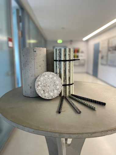
![Fig. 3: UHPFRC specimens: Types, denomination, and fabrication [13]](https://www.bft-international.com/imgs/1/5/9/2/0/8/6/HA_1064_Fig.03_Bild_3-41649127286ae188.jpeg) Figure: Leutbecher/Riedel
Figure: Leutbecher/Riedel
![Fig. 4: Loading direction and predominant fiber orientation (qualtitative) in compression tests on cubes [13]](https://www.bft-international.com/imgs/1/5/9/2/0/8/6/HA_1064_Fig.04_Bild_4-91144b067c720d54.jpeg) Figure: Leutecher/Riedel
Figure: Leutecher/Riedel
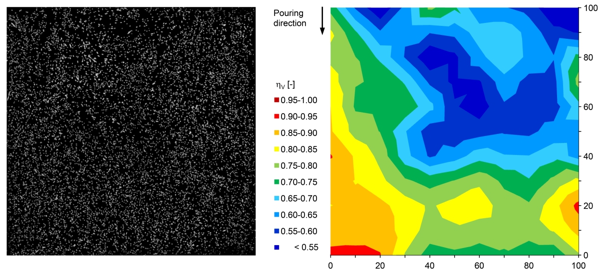 Figure: Leutbecher/Riedel
![Fig. 6: Mean values of compressive strength fcm of different specimens and test series and spread of individual test results [13]](https://www.bft-international.com/imgs/1/5/9/2/0/8/6/HA_1064_Fig.06_Bild_6_NEU-e19a38ad6404c31a.jpeg) Figure: Leutbecher/Riedel
Figure: Leutbecher/Riedel
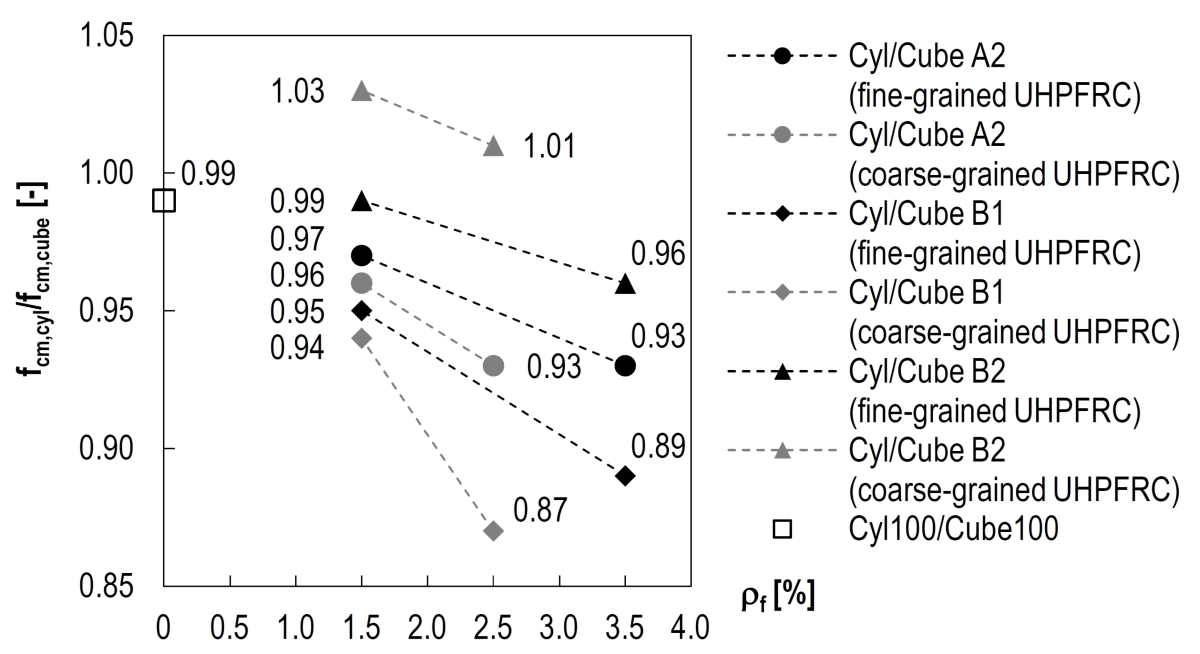 Figure: Leutbecher/Riedel


At present, a national technical approval or an approval on a case-by-case basis is required for structural applications of concretes >C100/115 as well as steel fiber reinforced concretes >C50/60. This holds true likewise to the application of ultra-high-performance concrete (UHPC), which is not yet regulated in Germany. This two-part paper presents the intended classification and reports on the backgrounds and test methods; please read the first part here.
1 Introduction
The spectrum of normal weight concretes covered by DIN EN 206 [1] and DIN EN 1992-1-1 [2, 3] ends at compressive strength class C100/115 in Germany at present. The characteristics and the application of steel fiber reinforced concrete are regulated in Germany by the DAfStb Guideline „Steel Fibre Reinforced Concrete“ [4] up to compressive strength class C50/60. A national technical approval of the Deutsches Institut für Bautechnik (DIBt) or an approval on a case-by-case basis granted by the supreme building authority is currently required for the structural application of (steel fiber reinforced) concretes of higher strength classes. This also applies to ultra-high-performance concrete (UHPC) [5], the application of which is not yet regulated in Germany.
The DAfStb Guideline „Ultra-High-Performance Concrete“ [6] is now aiming at an expansion of the range of applications covered by DIN EN 206 and DIN EN 1992-1-1 to (steel fiber reinforced) concretes with compressive strengths of significantly more than 100 N/mm². Besides the compressive strength, the axial post-cracking tensile strength is the second key strength parameter of ultra-high-performance fiber-reinforced concrete (UHPFRC). Based on these two parameters, concretes will be classified into compressive strength classes and performance classes. This paper presents the intended classification and reports on the backgrounds as well as test methods.
2 Classification of ultra-high-performance concrete in compression
2.1 Effect of the slenderness and size of specimens on the compressive strength of UHPC without fibers
2.1.1 Specimen geometries and shape factors
Like normal-strength concrete (NSC) and high-strength concrete (HSC), UHPC is intended to be classified into strength classes based on both the characteristic compressive strength of cylinders with h/d = 300 mm/150 mm after 28 days (fck,cyl) and the characteristic compressive strength of cubes with d = 150 mm after 28 days (fck,cube). However, these standard specimens exhibit very high ultimate loads which many testing machines used in practice cannot achieve. This justifies the need to allow determining the compressive strength of UHPC also on specimens with d = 100 mm, if required.
From building materials testing it is known that concrete compressive strength tests carried out on specimens with different slenderness and size provide varying strengths. The compressive strength of NSC, for example, measured on a cylinder with h/d = 300 mm/150 mm is only about 82 % of the compressive strength of a cube with d = 150 mm. A cube with d = 150 mm in turn typically reaches only about 92 % of the compressive strength of a cube with d = 100 mm. An increasing compressive strength at decreasing specimen slenderness can mainly be attributed to the restrain of lateral expansion owing to the rigid loading plates of the testing device and the resulting triaxial compressive stress state in large parts of the specimen. The effect of the specimen size is generally explained with the fact that the probability of weaknesses in the structure grows with rising specimen volume.
2.1.2 Experimental investigations to determine the shape factors of UHPC without fibers
With respect to the question about an influence of the specimen geometry on the compressive strength of UHPC, extensive tests were carried out as part of the DAfStb V 497 research project which are illustrated in [7, 8] in detail. The test program comprises a total of 8 series, including a series using NSC, a series using HSC and 6 test series using UHPC with different maximum grain sizes and compressive strengths fcm,cyl150 between about 30 MPa and 200 MPa (Table 1). The works were carried out at three different test institutes (Siegen, Kassel, Wiesbaden) in order to exclude any systematic falsifying effect. The inclusion of NSC and HSC should allow for a connection to the conversion factors known from literature for these concretes. Concretes without fibers were examined here exclusively.
Cylinders with h/d = 300 mm/150 mm (Cyl150), cylinders with h/d = 200 mm/100 mm (Cyl100), cubes with d = 100 mm (Cube100) and – in case of adequate capacity of the available testing machine – also cubes with d = 150 mm (Cube150) were tested in compression. Each test series comprised of 6 specimens per specimen geometry. In order to minimize spreads in compressive strength testing, also the load application surfaces of the cubes made of HSC and UHPC were carefully ground and all specimens made of UHPC were stored in water until testing.
2.1.3 Results of the compressive strength tests conducted on UHPC without fibers
Fig. 1 shows the results of the compressive strength tests. The column height represents the mean values of compressive strength fcm determined on the different specimen types of a series. The error indicator (black line) marks the respective spread of individual test results (min./max. value of compressive strength). The compressive strength fcm and the associated coefficient of variation V are specified in each column.
Fig. 2a shows the ratios fcm,cyl100/fcm,cube100 of the 8 test series as function of the cylinder compressive strength fcm,cyl150 to illustrate the effect of the specimen slenderness on the compressive strength. Whereas the cylinders made of NSC only obtain about 78 % of the cube compressive strength, the ratio for HSC rises to 84 %. With increasing compressive strength, the ratio approaches the value of 1.0 for both fine-grained and coarse-grained UHPC.
The effect of the specimen size on the compressive strength is shown in Fig. 2b. Here, the ratio fcm,cyl150/fcm,cyl100 is applied as function of the mean cylinder compressive strength fcm,cyl150. Showing ratios of between 0.95 and 1.02, fcm,cyl150 and fcm,cyl100 differ only slightly for all concretes tested.
Consequently, in case of UHPC without fibers, the specimen slenderness as well as the specimen size have only little impact on the result of the compressive strength test.
2.2 Influence of the fiber orientation and the fiber volume fraction on the compressive strength of UHPFRC
2.2.1 Anisotropy of fiber-reinforced concrete
The effects on the compressive strength which can be caused by the fiber orientation of fiber-reinforced concrete must be considered separately from the influence of the specimen slenderness and size. Depending on the specimen geometry, the rheological behavior of the fresh concrete and the production method, the fiber orientations can (locally) differ in test specimens and structural members considerably [9, 10]. As a consequence, the fiber-reinforced concrete behaves no longer isotropic but exhibits a different load-bearing behavior in tension as well as in compression depending on the loading direction [11, 12]. This aspect is particularly relevant for UHPFRC as in practice UHPFRC usually is applied with high fiber volume fraction.
In the context of the DAfStb V 501 research project [13] it was extensively investigated how different fiber orientations and fiber volume fractions impact the load-bearing behavior of UHPFRC. With regard to the classification of UHPFRC, it should be clarified how to assess the compressive strengths obtained in building material tests on standard specimens with different fiber orientations. Due to the production set-up, structural members may feature an even more aligned fiber orientation than the standard specimens (e. g., predominantly unidirectional fiber orientation in the bending compression zone of a beam). Thus, the transferability of the results obtained in building materials testing to this type of structural member should be checked as well.
2.2.2 Experimental investigations on UHPFRC
The test program comprised five test series with compressive strength tests on cylinders with h/d = 200 mm/100 mm and cubes with d = 100 mm made of UHPFRC. Table 2 gives an overview of the examined UHPFRC configurations. Series 1A is a repetition of Series 1 and served to verify the results. The study focused on fiber volume fractions ρf between 1.5 and 3.5 %, since a stronger anisotropy might reasonably be expected with an increasing fiber volume fraction [12]. In addition, the maximum aggregate size Dmax and the fiber length lf were varied within the typical range of practical application.
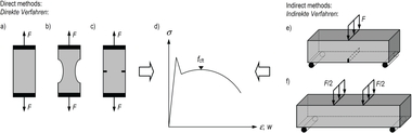
For each series, 9 cylinders (Cyl) and 12 cubes (Cube A) were cast in standard molds as well as three beams with l/b/h = 750 mm/100 mm/100 mm (Fig. 3). The beam molds were filled from one end of the formwork in order to provoke a predominantly unidirectional orientation of the fibers parallel to the longitudinal axis of the beam. Four cubes with an edge length of about d = 100 mm were sawn out of the center of each beam, so that another 12 cubes (Cube B) per series were provided for the compressive strength tests. The cylinders as well as 6 of the cubes (Cube A1) fabricated in standard molds and 6 of the cubes (Cube B1) sawn out of the beams were loaded in casting direction. The remaining cubes (Cube A2 and Cube B2) were tested perpendicular to the direction of casting. Fig. 4 shows the direction of loading for the four groups of cubes, qualitatively illustrating the orientation of fibers.
2.2.3 Evaluation of the fiber orientation
The evaluation of the fiber orientation was performed by means of an opto-analytical method [14] using the FiDiOr analysis software. Based on high-resolution, high-contrast photographs of polished cross-section surfaces, FiDiOr determines for each fiber its location in a Cartesian coordinate system as well as its orientation. The fiber orientation is characterized by the so-called fiber orientation coefficient. This coefficient corresponds to the cosine of the angle between the axis of the fiber direction and the normal direction of the sectional plane. With the opto-analytical method, it is determined by the ratio of the length of the minor axis of the ellipse (fiber diameter) to the length of the major axis of the ellipse of a fiber detected in the cross-section. The fiber orientation coefficient can be a value between 0 (orientation of the fiber in the sectional plane) and 1 (orientation of the fiber normal to the sectional plane).
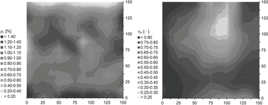
The evaluation of the mean fiber orientation coefficient hv according to [15] for the cross-sections of the beams (segments for the optical analysis in Fig. 3) showed values between 0.662 (coarse-grained UHPFRC) and 0.758 (fine-grained UHPFRC). This confirms the preferred orientation of the fibers in the flow direction of fresh concrete. Fig. 5 shows the evaluation of the prepared photograph of the polished cross-section of a beam of Series 1 (left) as an example and the distribution of the fiber orientation (right) determined here.
The test specimens fabricated in standard molds exhibited fiber orientation coefficients hv of 0.466 on average in casting direction and 0.552 perpendicular to the same, suggesting a preferred orientation of the fibers in the plane perpendicular to the casting direction. However, the anisotropy of these specimens is less pronounced than that of the beams. The application of a non-destructive induction method [16] led to similar findings. This method allows determining the mean proportional fiber orientation with regard to the three spatial directions of the different types of test specimen. The results of both measurement methods are shown in [13] in detail.
2.2.4 Results of the compressive strength tests on UHPFRC
The grinding of the load application surfaces and the storage in water were carried out as for the specimens made of UHPC without fibers. The results of the compressive strength tests are shown in Fig. 6. The column height represents the mean value of the compressive strength fcm of the respective type of specimen. The compressive strength fcm and the associated coefficient of variation V are specified in each column. The error indicator (black line) marks the respective spread of the individual results (min./max. value of compressive strength).
In case of fine-grained UHPFRC (Series 1, 1A, and 2), the cylinders show the lowest compressive strength. In contrast, the cylinders have slightly higher compressive strengths than the Cube B2 specimens in case of coarse-grained UHPFRC (Series 3 and 4). The Cube A2 specimens fabricated in standard molds and, as usual, tested perpendicular to the pouring direction range in all series between the Cube B1 and B2 specimens sawn out of the beams which have a stronger aligned fiber orientation than the formed test specimens. The compressive strengths of the Cube A1 specimens fabricated in standard molds and tested in the pouring direction do not indicate a clear trend.
In Fig. 7, the mean values of compressive strengths of different types of specimens shown in Fig. 6 are brought into relation and are illustrated as function of the fiber volume fraction ρf. The results of Series 1 and 1A are averaged for this purpose. The value of 0.99 for UHPC without fibers is obtained by averaging the ratios of the four test series 4, 5, 7 and 8 shown in Fig. 2a, where cylinder compressive strengths fcm,cyl150 between about 160 and 200 MPa were obtained, with using similar basic mix designs.
Whereas virtually any difference was determined between the compressive strength of specimens with slenderness 1.0 and the compressive strength of specimens with slenderness 2.0 on average in case of UHPC without fibers, the influence of slenderness gains in importance in case of UHPFRC with increasing fiber volume fraction. The broken lines, connecting the data points, illustrate this trend in Fig. 7 and, if theoretically extended, they approximately intersect the vertical axis on the level of UHPC without fibers. Different gradients of the individual lines indicate that the influence of the fiber volume fraction is more pronounced in case of coarse-grained UHPFRC.
The different trends of the ratios Cyl/Cube A2, Cyl/Cube B1 and Cyl/Cube B2 as function of the fiber volume fraction is obviously attributed to the different fiber orientations in the different types of test specimens. The influence of the fiber volume fraction is particularly pronounced if the fibers are predominantly oriented perpendicular to the direction of loading (Cube B1). Whereas the failure of Cube B2 specimens in consequence of fibers predominantly oriented in the direction of loading is hardly affected. This leads to the fact that Cube B2 specimens in case of coarse-grained UHPFRC show even lower compressive strengths than cylinders with a „favorable“ fiber orientation.
2.3 Conclusions for the classification of UHP(FR)C in compression
While the compressive strength of cylinders and cubes made of UHPC without fibers differs only marginally, the compressive strength of cylinders and cubes fabricated in standard molds showed differences of up to 13 MPa for UHPFRC with very high fiber volume fraction. Based on these results, the compressive strength to be verified on cubes may conservatively be defined as fck,cube = fck,cyl + 15 MPa for UHP(FR)C. With characteristic cylinder compressive strengths fck,cyl of 130 MPa, 150 MPa and 175 MPa, which were adopted from the French standard NF P18-470 [17], the draft of the DAfStb Guideline „Ultra-High-Performance Concrete“ provides the concrete strength classes C130/145, C150/165 and C175/190.
As the actual difference between cylinder and cube compressive strength depends on the fiber volume fraction, using cylinders for compressive strength testing can be economical, in particular, for low fiber volume fractions. In any case, the load application surfaces of the test specimens should be ground very carefully. This is also recommended for cubes in case of doubt. In order to minimize spreads among the test results, it is moreover necessary to store the specimens in water after demolding until testing – unlike usual practice in Germany.
If specimens with d = 100 mm are used in conformity tests, a reduction of the measured compressive strength by 5 MPa is recommended for the conversion to the corresponding reference specimen with d = 150 mm. This recommendation is based on the results shown in Fig. 1 and Fig. 2b. It adequately takes account of the only minor overall influence of the specimen size on the compressive strength.
Due to the production setup, the anisotropy caused by the fiber orientation in structural members or parts of them can be considerably more pronounced than in standard specimens used in building materials testing. Depending on the direction of loading, the compressive strengths of cubes sawn out of beams made of fine-grained UHPFRC differed by up to 8 % and about 15 MPa, respectively, and those of coarse-grained UHPFRC by up to 15 % and 26 MPa, respectively. In this regard, a predominantly unidirectional orientation of the fibers in the direction of compressive loading turned out to be critical. The fibers oriented in this way hardly influenced the fracture process. Therefore, the compressive strength of these cubes – independent of the fiber volume fraction – hardly differs from the cylinder compressive strength (cf. ratios Cyl/Cube B2 in Fig. 7). Against this background, a particular reduction of the cylinder compressive strength appears unnecessary, in order to take an „unfavorable“ fiber orientation in structural members into account. Hence, the cylinder compressive strength is a conservative estimation of the uniaxial concrete compressive strength valid for all parts of a structural member, in particular such with a predominantly unidirectional fiber orientation perpendicular to the direction of compressive loading.
REFERENCES/LITERATUR