BIM in the precast industry
-
Fig. 1 Precast factory building: columns, girders,...
-
Fig. 2 3D reinforcement of a highly reinforced...
-
Fig. 3 Element plan: portion of the plan...
-
Fig. 4 Element plan: layout editor to prepare...
-
Fig. 5 Transfer of complex elements and automated...
-
Fig. 6 Balcony slab; inclined areas and edges...
-
Fig. 7 Highly reinforced column; routing of...
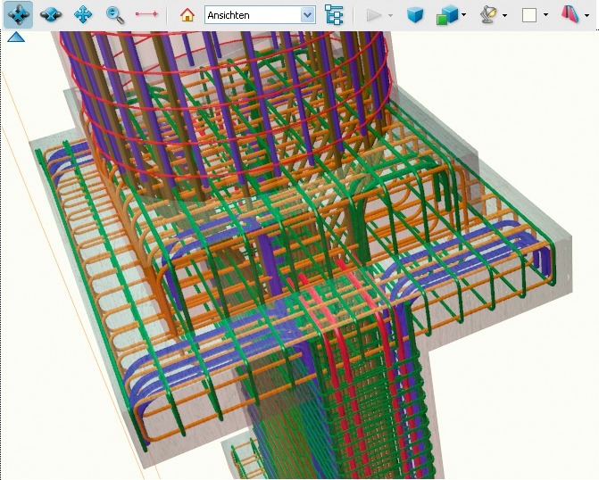
The concept of BIM (Building Information Modeling) describes an integrated, end-to-end process for the design, building and use of structures. As an extension to conventional CAD systems, BIM creates the basis to convey consistent information to all parties involved in a timely fashion. There is hardly any other CAD application where BIM plays a more significant role than in precast element design. The design, production, delivery and assembly of elements are often taken over by one and the same contractor so that an integrated solution results in a tangible immediate benefit.
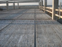
Plants with circulation lines and robots
First of all, BIM means 3D design. In addition, non-geometrical information can be described, such as the surface quality of a precast unit. This makes it possible to perform any subsequent work step directly without having to enter data again. The advantage is obvious: no new data input, no error sources, immediate calculation.
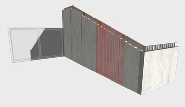
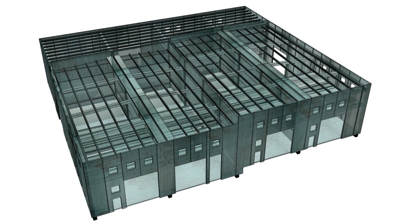
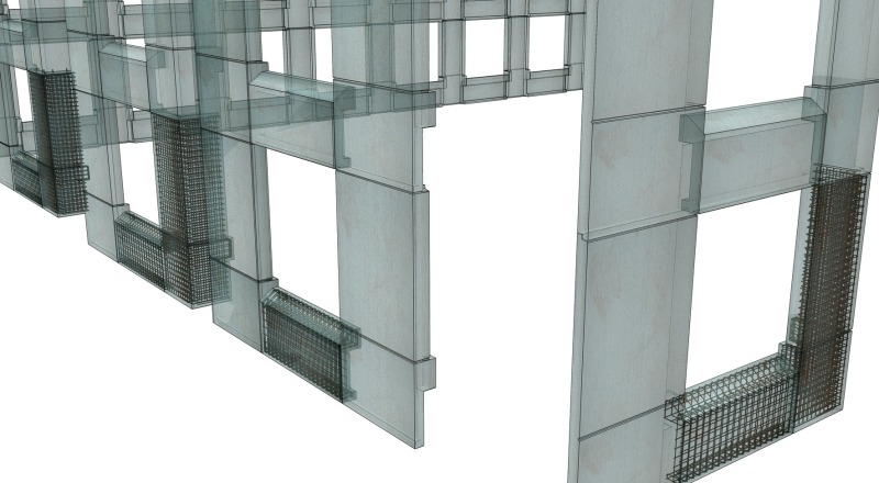
Given all the benefits, these 3D applications have already gained a major share in designing and producing flat elements such as floor slabs and walls, which are manufactured with a high degree of automation. As the output of the design exercise, the Allplan Precast CAD system does not only deliver plans but also the complete range of information required for production and invoicing. This creates the foundation for an integrated process.
BIM and plans
Today and in the future, plans are and will be required. For this reason, features are needed that ensure the automated preparation of plans, as in the case of floors and walls.
A 3D model is generated in the first planning step (Fig. 1) irrespective of whether the program deals with floors, walls or structural elements.
Precast plants mostly use an approach in which the building is created as a precast model that includes the individual precast elements. In many cases, embedded parts are considered in the design, too, for assembly purposes in order to ensure a smooth assembly process. In the following steps, the formwork and reinforcement plans are prepared for the individual precast elements. In this regard, Allplan Precast provides a unique technology – the “element plan”.
The element plan technology makes it possible to click on the precast element only once to create an almost perfect plan in a fully automated fashion: views, sections, dimensions, stamp field, labels (Fig. 2 and 3).
To ensure that all types of precast elements appear in their usual layout, a graphic layout editor is provided to design any customized plan template in a simple fashion.
Graphic plan layout tool
For a certain type of precast element, such as a column, a generally applicable plan layout is defined, including sections, views, chains of dimensions, labeling, keys and stamp field (Fig. 4). For this purpose, the appearance and visual structure of the plan is determined. This single preparation step ensures that legible, project-specific plans are created in which the geometry, reinforcement, embedded parts etc. can be activated separately. In all probability, the automatically created plan will not have to be revised for simple elements. Even for the most complex elements, a clearly structured, company-specific layout is generated that can then be developed further with all the required attention to detail.
CAD in CAD – BIM must not be a one-way street
This plan layout is used to design the reinforcement and to incorporate the embedded parts. This is simply due to the fact that the design of the reinforcement is easier in a 3D projection with views and sections than in an isometric drawing. A stirrup can easily be added to a section whereas the laying pattern is best added to the view. The end result is, however, a 3D reinforcement cage. This means that any section that may be required in a subsequent step is automatically correct. Wherever the designer works – in the model or in the element plan – all information is carried along simultaneously in each display.
BIM with Allplan Precast is thus no one-way street where the model needs to be opened to modify data because the options for modification are too limited in the automatically generated plan. This program is a “CAD in CAD” solution that works both ways and delivers consistent plans and data.
Tried and tested 2D methods in the 3D model
In 2D, it is absolutely easy to copy an item. By contrast, any copying that involves a complex structural reinforcement arranged around a window opening – add to this an inclined wall – is hardly feasible, or not feasible at all, in 3D. Spacings, angles and the exact depth of the layer would have to be determined, and most designers are quite right to consider this task too demanding. For this reason, a transfer feature takes care of this task in a single step and inserts the reinforcement in its correct position, complete with embedded parts (Fig. 5).
A balcony slab with the top side being drained in different directions and at various gradients is difficult to design even in 2D. This is much easier to achieve in the model if a level modeling tool exists that automatically interlinks with the vertical structures, of if, conversely, vertical structures expand automatically up to this level (Fig. 6). Such features more than compensate for the advantages of 2D and make a valuable contribution towards ensuring guaranteed quality and efficiency.
Master prints – tried and tested practices revived
Still familiar with the master print technique? Once made obsolete by CAD, this technique is now becoming increasingly significant again in conjunction with BIM.
First of all, the automation of plan generation means that an automated plan is created for each precast element. This is common practice when using shuttering robots to produce floors and walls while other baseline information is needed for structural precast.
Identical precast parts must be captured in one and the same plan, including the number of items. This means that Allplan Precast checks the precast elements and ascertains if the geometry, reinforcement, embedded parts and attributes such as concrete quality are exactly the same. In such a case, these precast elements are shown on only one element plan, complete with the number of items to be produced.
Almost certainly, some or another element that belongs to such a group will have to be modified. In that case, the program ensures that the labeling on the overview and the number of items indicated on the element plans are adjusted automatically. This approach guarantees that the building model and assembly plan, as well as the individual plans for precast element production, always correspond in terms of labeling and number of items. In other words, this is change management made easy.
A new plan is generated whenever the model is modified. If a manually processed plan is already available for the precast element, it would be a nuisance to make this work null and void, which is why Allplan stores such manual additions to a large extent. The designer only takes care of changes that need to be made, for example, as regards the reinforcement.
Yet Allplan Precast has even more to offer: a plan processed in this way can be easily transferred to a similar precast element so that only minor modifications need to be made to create a correct plan for the new element – just like in the olden days of master prints. As a matter of course, the new system avoids all the disadvantages previously encountered with master prints.
Organization
BIM creates the basis to convey consistent information to all parties involved in a timely fashion. Allplan Precast serves to carry out the design work. This means that, at the end of the process, virtual precast elements have been created in addition to all the usual outcomes of the design exercise, such as the drawings and bills of materials printed on paper. These virtual elements are easy to view and assess, but who is able to handle them properly? Since PDF has become a generally accepted format, such files are a useful tool, all the more so because almost every computer user has at least installed a PDF viewer and knows how to use it.
Without any difficulty, Allplan is able to import, structure and export PDF files. In addition, Allplan saves its data using genuine Adobe technology so that any “non-CAD user” may not only view the 3D models but is also able to measure them, to add notes and to place sections him-/herself.
Precast plants use PDF 3D to make their offers more transparent. The quality manager uses PDF 3D to check the virtual precast element against the element that is being produced (Fig. 7). Customers at the forefront of innovation have installed a computer screen at the production line and exclusively use PDF files for both plans and models.
ERP at the precast plant – from design to assembly
Today, the classic ERP (Enterprise Resource Planning) systems support tasks in sales, process planning, production, delivery and assembly. However, the flow of information and data between the various systems used in design, production and ERP mostly relies on very simple data interfaces and the transfer of data files.
Yet the future will be characterized by a continuous flow of information and alignment of data that simplifies internal organization at the factory whilst eliminating error sources. In addition, using the virtual elements created, tasks such as delivery, production and assembly planning will no longer be carried out on the basis of rows of figures. Instead, graphic displays will be used because all the information pertaining to the precast element will be visible and available. The PP Manager processes these tasks both graphically and numerically. The initial experience gained by pilot customers demonstrates that this is the right path to follow.
Summary
To date, the use of BIM in construction has largely remained a vision. Since a cross-disciplinary effort is required, liability issues often stand in the way of a rapid development. By contrast, BIM has already become a mission at precast plants. Highly automated plants that produce floor slabs and wall units benefit from the advantages offered by integrated solutions. With Allplan Precast, there is no reason not to extend this approach to structural precast.


