A basic element as punching shear and bond reinforcement for all semi-precast floor slabs with in-situ concrete topping of various heights
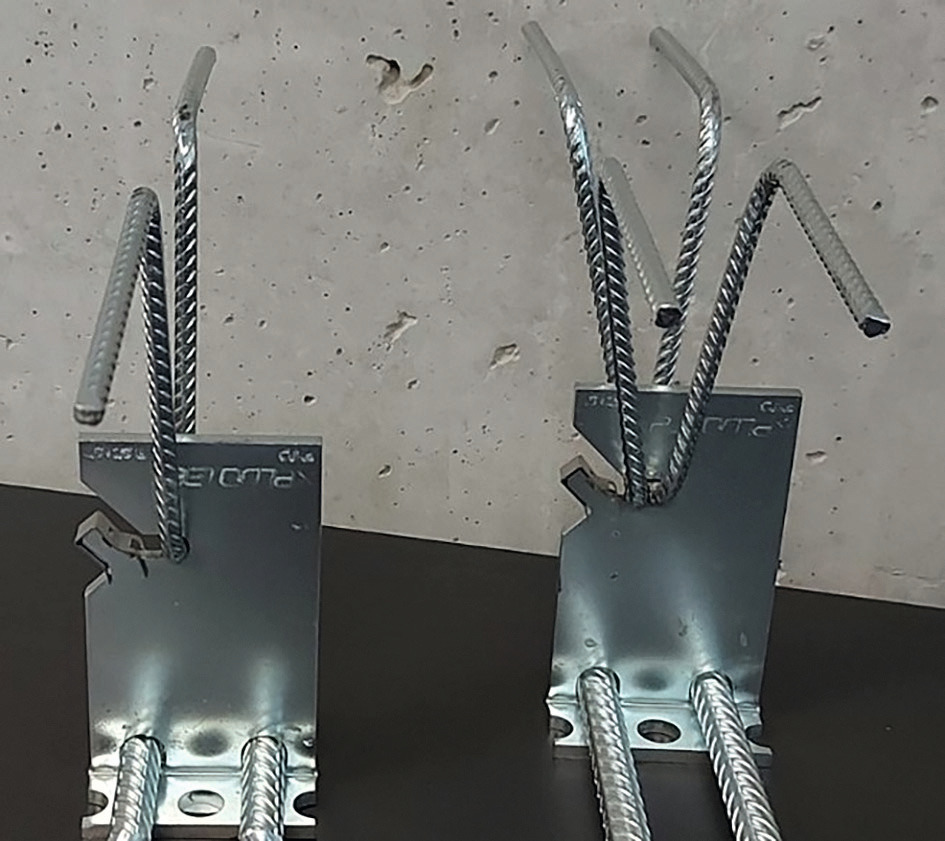 Figure: Betomax
![Fig. 02: Input mask of the design software from Betomax Systems [3]](https://www.bft-international.com/imgs/1/9/7/9/0/7/9/Fig._02-57dc7468fb2a0611.jpeg) Figure: Betomax
Figure: Betomax
 Figure: Betomax
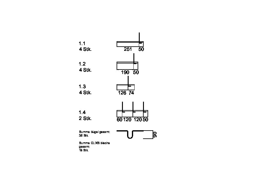 Figure: Betomax
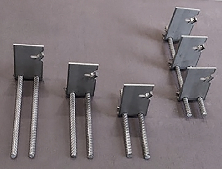 Figure: Betomax
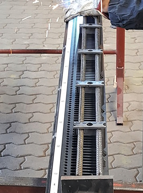 Figure: Betomax
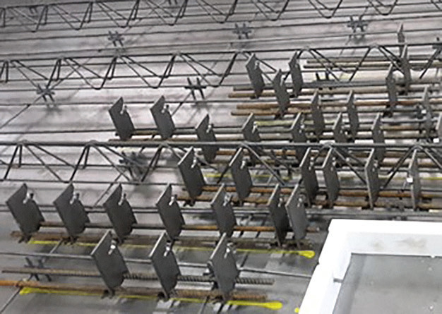 Figure: Betomax
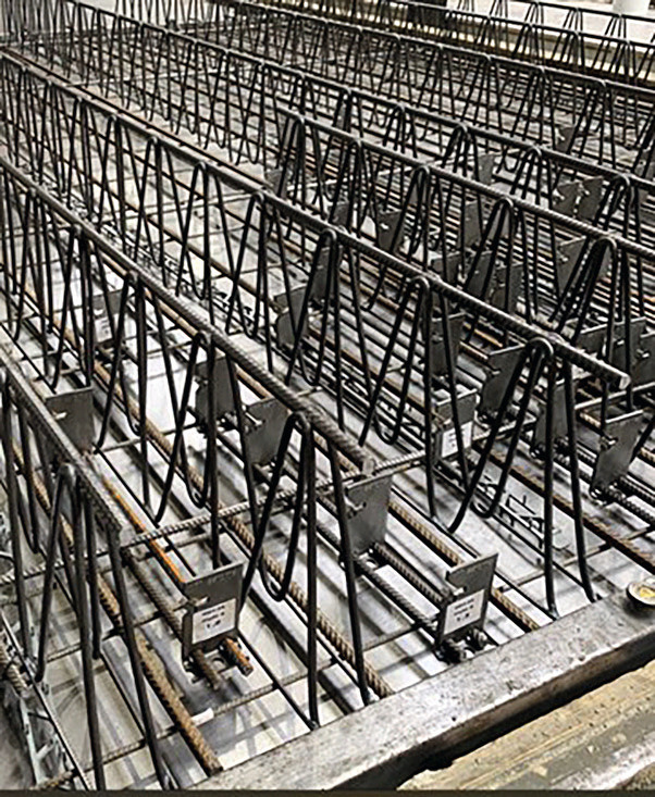 Figure: Betomax
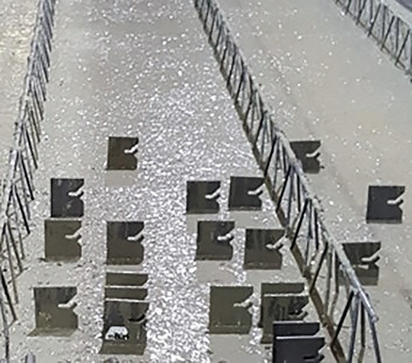 Figure: Betomax
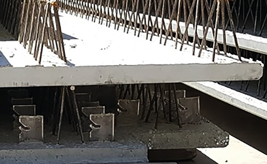 Figure: Betomax
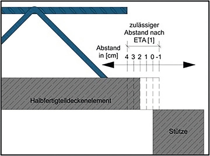 Figure: Betomax
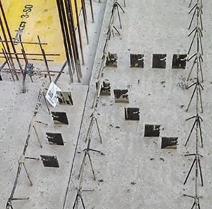 Figure: Betomax
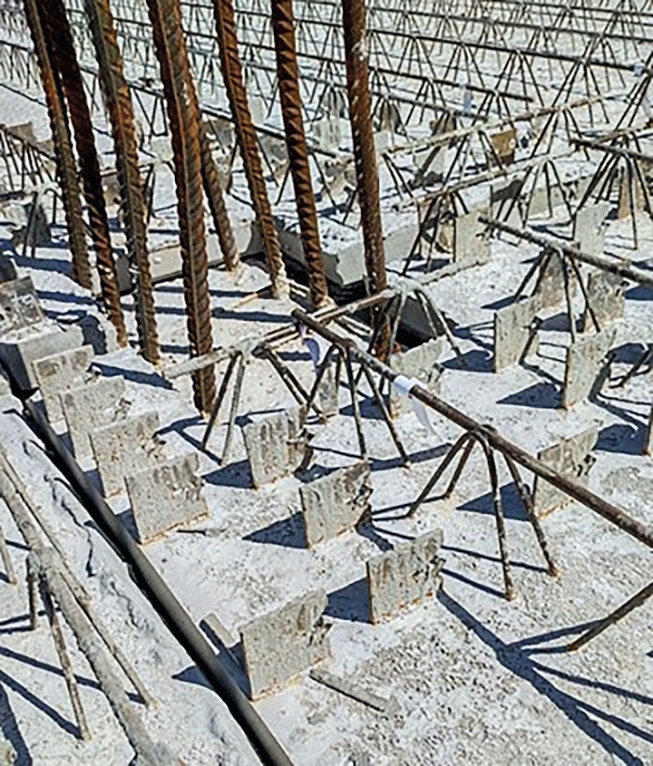 Figure: Betomax
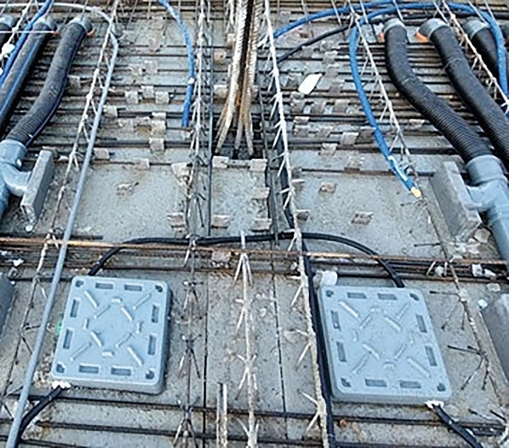 Figure: Betomax
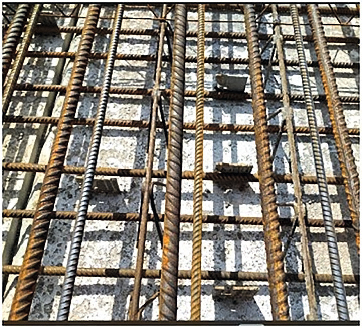 Figure: Betomax
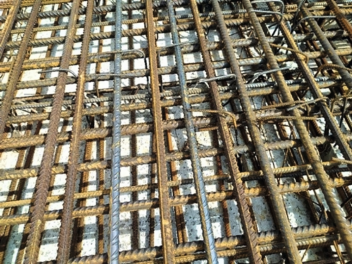 Figure: Betomax


The structural requirements for concrete structures have continued to increase in recent years. This report discusses use of the punching shear and bond reinforcement system for manufacture of semi-precast floor slabs according to the ETA 19/0310 European Technical Assessment ETA 19/0310 dated 21 February 2022 [1].
The structural requirements for concrete structures have continuously increased in recent years. Flat slabs and slender columns quickly present structural engineers with the problem of verifying their punching shear resistance. The bearing capacity of the concrete in flat slabs is very often not sufficient, and verification for punching shear succeeds only with use of a reinforcement system such as CLIXS from Betomax Systems.
This report describes the use of the punching shear and bond reinforcement system according to the ETA 19/0310 European Technical Assessment dated 21 February 2022 for manufacture of semi-precast concrete floor slabs.
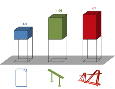
CLIXS can more than double the punching shear resistance of flat floors of the concrete bearing capacity. This reinforcement system, patented throughout Europe [2], moreover, assumes a large share of the transmission of the bond force in the joint between the semi-precast element and the in-situ concrete topping.
Technical description of the reinforcement system
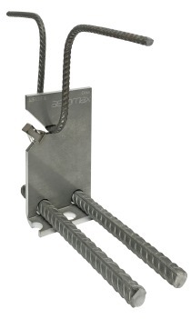
The CLIXS 2.0 punching shear and bond reinforcement system consists of one or two stirrups of conventional reinforcing steel and one folded L–sheet (Fig. 1). The stirrups are hung across the slanted extended hole in the steel sheet and are secured with a spring clip. The position of the L-sheets in the formwork is ensured by two conventional reinforcing steel elements of 12-mm diameter. These are inserted at the bottom through the predrilled boreholes in the L-sheets and can be used as additional reinforcement or can be credited as part of the flexural reinforcement provided.
Detailing
For reinforced-concrete elements, strength classes C20/25 to C50/60 are approved.
The heights of the floor slabs are specified depending on the number of stirrups per L-sheet.
L-sheet with one stirrup: 18 cm ≤ h ≤ 40 cm
L-sheet with two stirrups: 18 cm ≤ h ≤ 110 cm
The heights of the stirrups result from the heights of the floor slab h and the concrete cover cbelow and cabove:
Floor slab height < 24 cm: hStirrup = (h – cabove – cbelow – 7,5) x 1.06 [cm]
Floor slab height ≥ 24 cm: hStirrup = (h – cabove – cbelow – 6,5 [cm]
Design software
The design can be carried out in just a few simple steps with the free software from Betomax Systems [3] (Fig. 2). Calculations according to the ETA 19/0310 European Technical Assessment dated 21 February 2022 [1] are performed on the basis of the design for stirrups for punching shear design according to EC 2 and can be easily understood and verified manually. Application-friendly parameters such as element joints and blockouts can be easily included in the design software.
The individual calculation steps for punching-shear and bond verification can be taken from the website of the company Betomax Systems by using the QR code (Fig. 3). An example of manual calculation for an internal column is described in detail.
All calculation steps as well as the distribution of embedded parts and the parts list of the linear elements with the exact dimensions are listed in the result printout (Fig. 4). Accordingly, all information is provided as required for manufacture of the aligned L-sheets for production of the linear elements.
In the software, selection takes place of the extended longitudinal bars to facilitate installation of the L-sheets as linear elements (Fig. 2). To ensure positional exactness, the elongated longitudinal bars are installed on the edge formwork and/or on the blockouts of columns. The linear elements in Figure 5 accord with the parts list in Figure 4.
Manufacture of the linear elements with aligned L-sheets
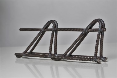
In the plant, the L-sheets can be threaded by means of a toothed gear onto two steel bars of Ø 12 b to form a linear element and are secured in their positions with adhesive points or tie wire (Fig. 6).
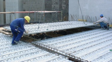
Placing the linear elements onto the formwork in the plant
A plotter or laser projector controlled by the master computer marks the positions of the line elements on the switching table during production in the factory. Here, the information from the calculation software [3] can be read in directly, e.g. through a BIM interface. In the next step, the linear elements are installed on spacers between the lattice girders as specified (Fig. 7).
Due to the linear – as opposed to star-form – arrangement of the punching shear elements, collision-free installation of the floor slab reinforcement is possible without difficulty. The linear elements with L-sheets are positioned parallel in the same position as the longitudinal reinforcement and the main lattice girders (Fig. 8).
Casting the linear element into the concrete
In the precast plant, the steel sheets are cast, with position certainty, into the concrete together with the lower reinforcement and the lattice girders (Fig. 9).
Storage and transport of the semi-precast floor slabs
No stacking aids are required for transporting and storing the semi-precast floor slabs, because the embedded steel sheets do not extend beyond the lattice girders. The CLIXS L-sheets in the semi-precast floor slabs are impact-protected and do not affect storage, loading or transport and intermediate storage at the construction site (Fig. 10).
Requirements for installation
The distance between the face of the column and the semi-
precast floor slab can range between 4 and -1 cm (Fig. 11). If the slab element is directly supported by the column, the joint between the column and the slab must be completely mortared. This ensures transmission of the loads from the stories above.
Semi-precast floor slabs installed at the construction site with L-sheets
Fig. 12 shows semi-precast floor slabs installed with CLIXS L-sheets at a wall corner and, in Fig. 13, for an internal column.
Fig. 14 shows that L-sheets can be used without difficulty as punching shear reinforcement in floor slabs, even with numerous different embedded components.
Installation of the reinforcement and hanging of the stirrups at the construction site
The CLIXS L-sheets do not interfere with installation of the lower reinforcement on the concrete of the semi-precast floor slabs, or with installation of the upper reinforcement on the lattice girders (Fig. 15).
After the upper reinforcement has been installed at the site, the stirrups can be “CLIXSted into the long hole of the L-sheets from above and placed on or at the upper reinforcement layer without having to be additionally secured. Following placement,the stirrups can be inclined up to 30° to either side (Fig. 16).
REFERENCES/LITERATURVERZEICHNIS