Precast concrete seawall protects South African coastal town
Over the past 10 years, high seas and wave action in False Bay have impacted on beach structures located between Gordon’s Bay and the mouth of the Eerste River. A two-year research programme led to a decision to replace the existing Strand seawall with a 3 km precast concrete seawall in a triple-phased construction programme.
Over the past 10 years, high seas and wave action in False Bay, situated off the Western Cape peninsula in South Africa, have impacted on beach structures located between Gordon’s Bay and the mouth of the Eerste River.
Sections of a seawall adjacent to Beach Road in Strand were breached between April 2006 and June 2007, causing damage to pavements and streetlights, and threatening to flood basements in some of the side streets. Despite remedial measures taken by the City of Cape Town (CCT), which included replacing a broken seawall with a temporary revetment on the eastern beach, the seawall to the west at the Sarel Cilliers intersection continued to be overtopped.
This ongoing damage to the Strand seawall and other structures prompted CCT to appoint PDNA (later acquired by Mott MacDonald) to undertake a detailed coastal study from Gordon’s Bay to the mouth of the Zeekoevlei canal outlet in 2011. The study had a threefold objective: to realize a better understanding of coastal zone dynamics in a context of rising sea levels; to assess the condition of coastal structures along the 38 km of coastline to Zeekoevlei, especially their performance in relation to wind-blown sand and beach-wall overtopping; and to propose solutions for the Strand beachfront.
Mott MacDonald assembled a team of coastal research specialists including Geoff Toms, head of Ports and Coastal Engineering at the University of Stellenbosch, and Piet Badenhorst, a specialist in dune management.
New 3 km precast concrete seawall
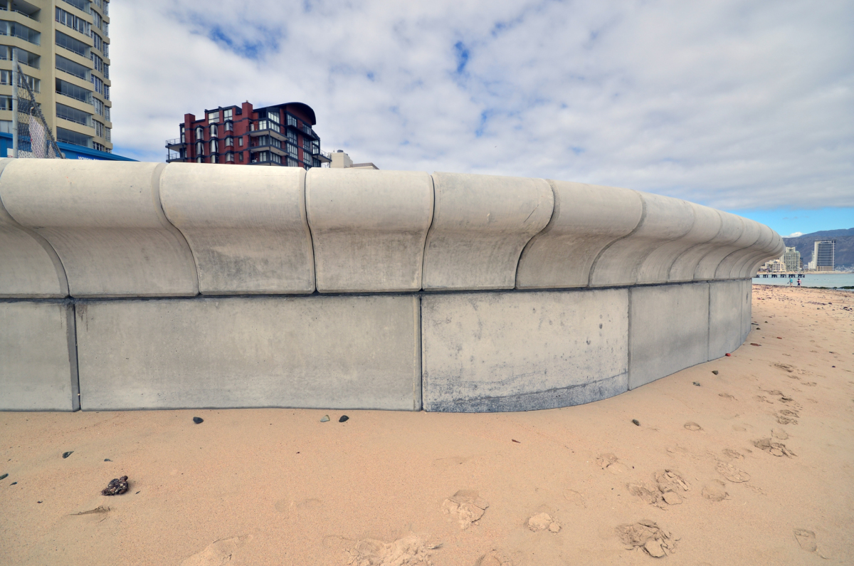
This two-year research programme led to a decision to replace the existing Strand seawall with a 3 km precast concrete seawall in a triple-phased construction programme.
“The choice of precast concrete units for building the seawall was an engineering decision based on the need to build quickly and to achieve high standards in durability and finish qualities,” commented Mott MacDonald specialist consultant, Tony Cooksey.
“Manufacturing precast elements in a factory away from the marine environment made it easier to achieve the high specifications on a consistent basis. It was also more cost-effective.
“The height of the precast wall was calculated through the numerical modelling of deep-sea wave conditions close to the near-shore and by physical modelling of the design wave (significant wave) against allowable overtopping rates. The physical modelling included flume experimentation at Stellenbosch University’s Coastal Engineering Laboratory where different coastal defences were assessed against the allowable overtopping rates. Key factors in the elevation of the seawall also included future climate changes and line-of-sight for the public enjoyment of the beach front,” Cooksey added.
The amount of water and wind-blown sand, which could overtop the walls, were crucial research elements. Given that this is a holiday destination, aesthetic considerations also played a significant role in the design brief.
“For instance, we had to restrict the height of the walls as measured from the promenade surface to the top of the walls to give promenade strollers unimpeded view of the beach and the sea. And even though Beach Road slopes gradually from the west to the east, the elevation of the top of the wall will remain constant.
“The great bulk of the wall is buried below ground and the visible portion as viewed from the beach will vary constantly, being dependant on the vagaries of shifting beach sands. All our calculations, based on both our numerical and physical models, indicated that 3.5 m above zero land levelling datum was our optimum height. This, and the horizontal alignment of the wall in relation to the coastline, was arrived at after extensive debate with environmental advisers and City Parks,” said Cooksey.
Highly flexible solution
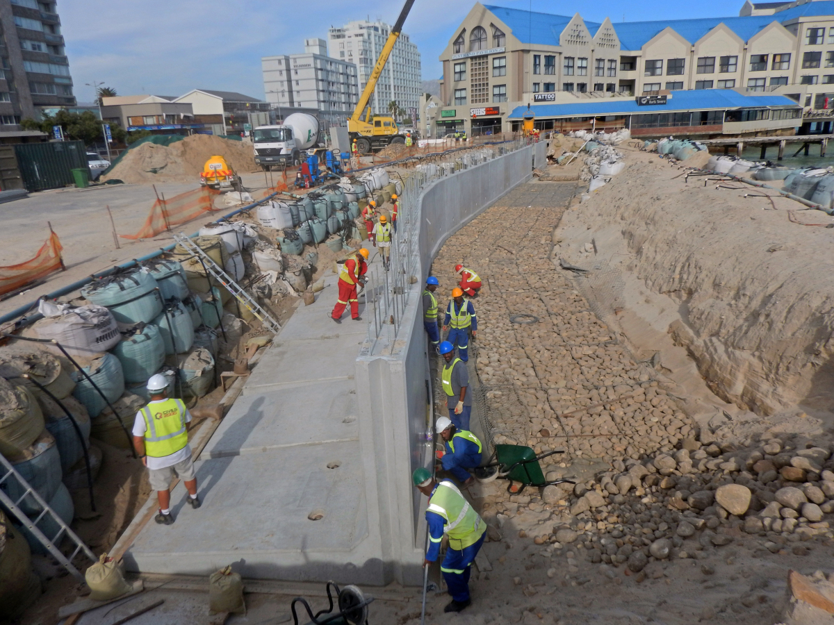
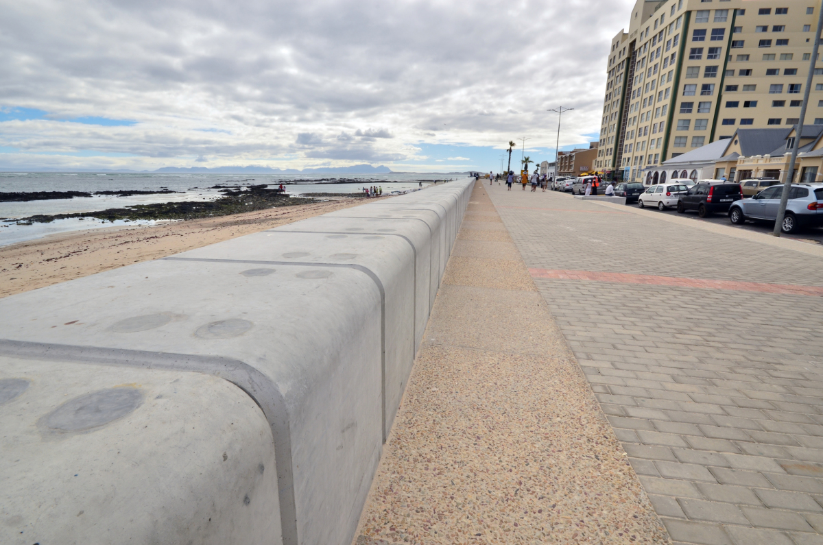
Construction of Phase 1, which is 1.1 km long and runs from the Strand Pavilion to a point between Burnard and Da Gama Streets, began in January 2016 and was completed at the end of November 2017. Phase 2 began where Phase 1 ends and will provide protection up to a point near the Strand Surf Life Saving Club where natural vegetation would then provide protection to infrastructure. Phase 3 will cover the area from Strand Pavilion to Greenways.
As Mott MacDonald marine coastal engineer Brenton Heron says, an L-shaped gravity wall was an attractive option for a number of reasons.
“It is a highly flexible solution as it can be integrated with various other coastal protection measures such as rock revetment or beach nourishment. It can also be easily integrated with a promenade, as in the case of Strand, as well as other beachfront amenities. However, varying founding conditions at the Strand beachfront, and the placement of the L-shaped units in a challenging environment, made achieving a uniform vertical and smooth horizontal alignment one of our main construction-related challenges. During the design stage it was envisaged that achieving a tight tolerance on the works would be challenging. Therefore the coping was designed to take in the differences in tolerances and to deliver a smooth wall alignment, both vertically and horizontally.”
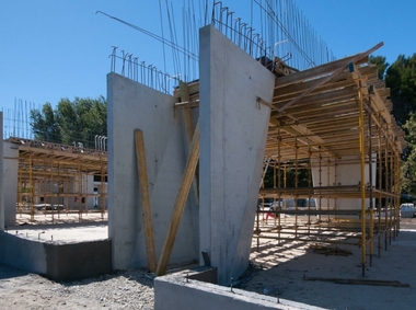
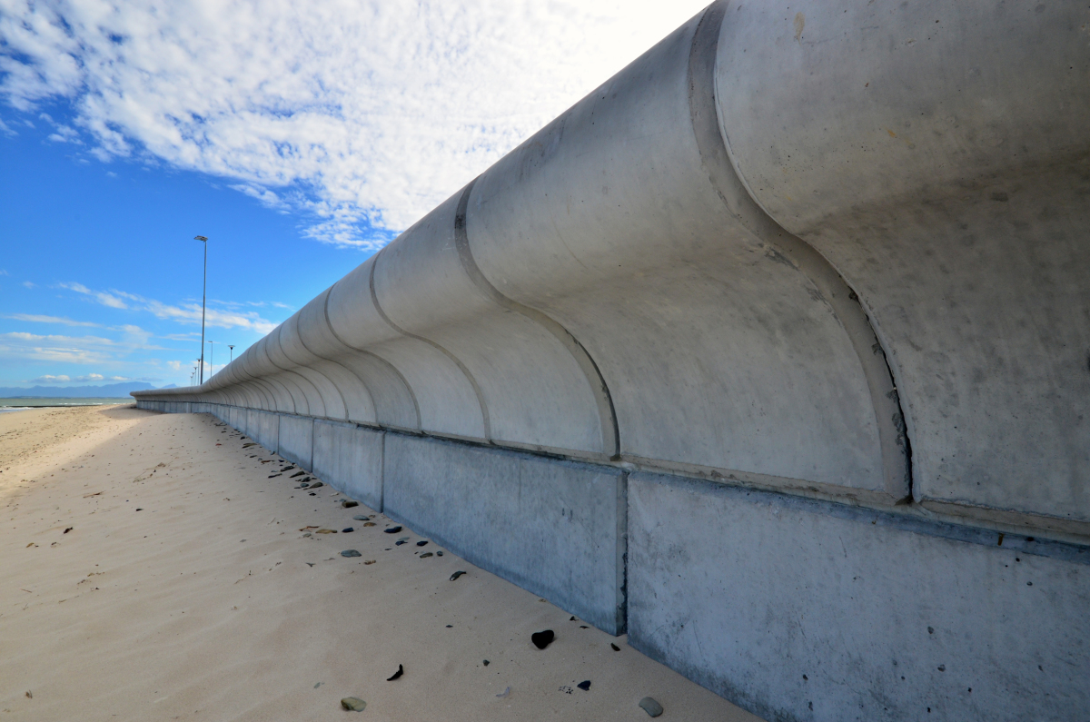
Three main structural elements
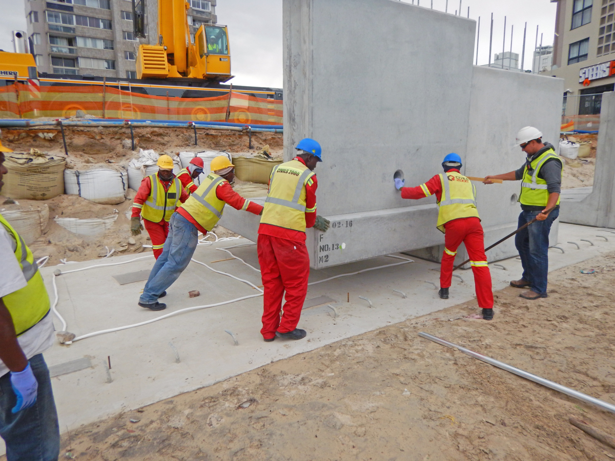
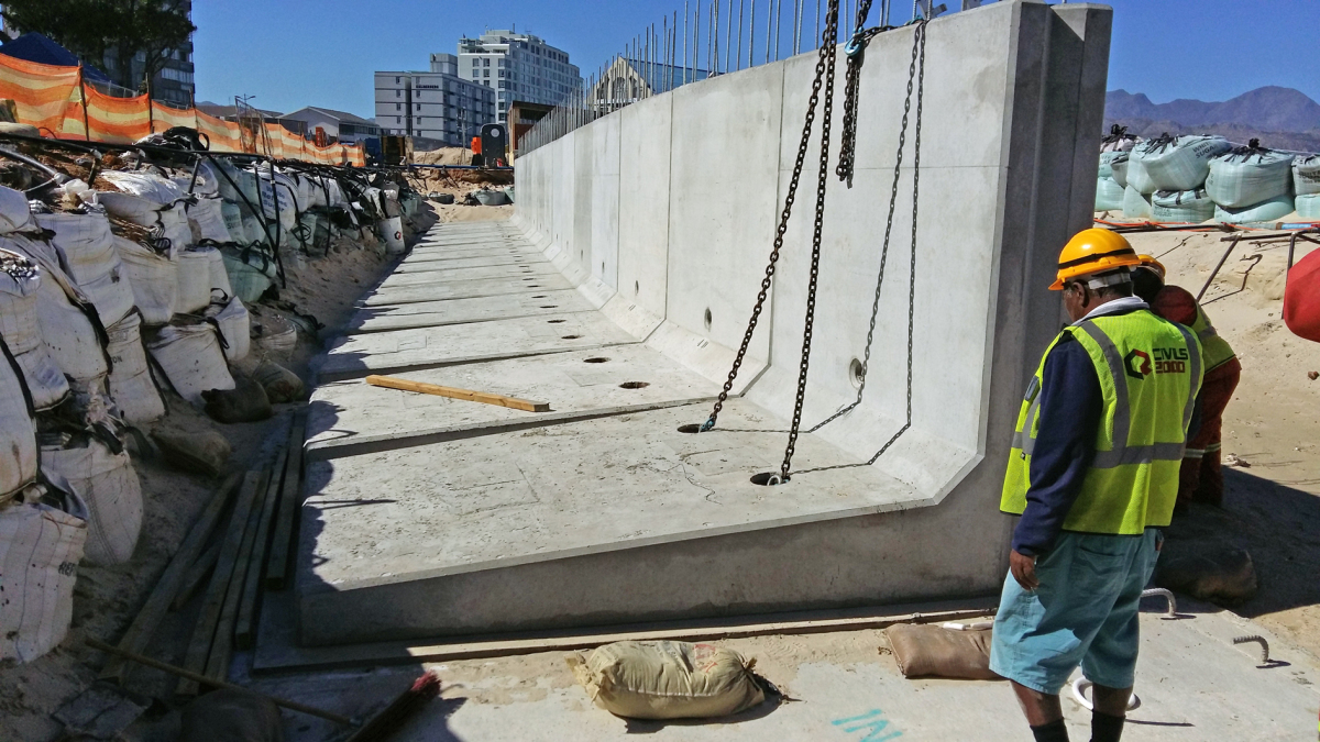
The walls contain three main structural elements. Starting from the bottom they are: an in-situ concrete mass-concrete foundation which, depending on the bedrock was laid on varying founding conditions; L-shaped precast concrete units which weigh between 14 and 16 t and measure 3.5 m (length), 2.65 m (height), and 2.4 m (width); and curved 1.5 t precast concrete coping units, 835 mm high and 795 mm wide. On certain sections, there is a fourth element, namely, rock-based reno mattresses which are 4 m long and 300 mm deep. They were placed at the toe of all L-shaped units not founded on bedrock and provide scour protection.
“Without de-watering, much of the sand is water-logged and during construction de-watering has to be continuous,” Heron commented. “Where sandy saturated conditions persisted, a 350 mm pioneer layer of rock, wrapped in geotextile fabric, provided a stable surface for casting the concrete foundation. In drier sections the mass concrete foundation was cast directly onto sand or rock or a combination of the two.”
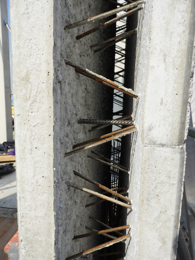
The coping units were cast with vertical corrugated sleeves 80 mm in diameter. This enabled the coping units to be lowered into position over the galvanized rebar, which protruded from the L-shaped units. The sleeves were then filled with grout to secure the coping into position.
Concrete Units cast 494 L-shaped units and 1,600 coping units. Approximately 100 L-shape units were cast with curves to accommodate the curvatures of the walls of which there are 30 different types. Some 200 curved coping units were cast in eight different shapes. These were optimized by using innovative variable molds.
Laboratory results extremely satisfactory
Commenting on the casting process, Concrete Units manager, Brian Cook, observed that a very high stan-dard of concrete was a project specification.
“The quality rating of the concrete centred around four durability indices and we submitted our concrete mix design to the concrete laboratory at the University of Cape Town for verification. The results were extremely satisfactory and were higher than what is normally associated with a marine environment. For instance, we were working on a permeability index of 9.6 and achieved 10.24.
“Another quality requirement was the absence of blemishes and blow holes on the surfaces of the units and we changed our casting methodology to ensure this. Moreover, instead of self-compacting concrete we opted for a high slump alternative.
“Initially we batched the concrete ourselves using a 26 mm aggregate and pulverized fly ash from the province of Gauteng and achieved a strength rating above the required 40 MPa. We subsequently gave our mix designs to Megamix who supplied us with the concrete. An exposed aggregate finish was considered as an option for the coping units but ultimately off-shutter finishes were chosen for both units. This simplified matters and gave matching finishes on both units.
“This project also called for 75 mm cover of the rebar. We had to have the cover blocks cast locally because a weak rand made imported units too expensive. They were very heavy-duty units with very low absorption properties and have the same durability properties as the concrete used on the L-shaped and coping units. We used pulverized fly ash and many other special materials to achieve a cover-block strength rating of over 50 MPa.”
Concrete Units also designed and built lifting systems for the loading and off-loading of the L-shape and coping units.