Safety advantages with system solutions
![Fig. 1 Examples for prefabricated rebend connections [9], [10].](https://www.bft-international.com/imgs/103946006_d6f39ae9d9.jpg)
![Fig. 2 Keying according to DIN 1045‑1 [1].](https://www.bft-international.com/imgs/103946009_edb61f239b.jpg)
![Fig. 3 Definition of the various design situations [2].](https://www.bft-international.com/imgs/103946029_cba8bddeb9.jpg)
![Fig. 4 Erection flow [10].](https://www.bft-international.com/imgs/103946020_2928396c80.jpg)
![Fig. 5 Examples of prefabricated flexible reinforcement connections [8], [11].](https://www.bft-international.com/imgs/103946050_f0511b1001.jpg)
![Fig. 5 Examples of prefabricated flexible reinforcement connections [8], [11].](https://www.bft-international.com/imgs/103945999_f0e349b809.jpg)
![Fig. 5 Examples of prefabricated flexible reinforcement connections [8], [11].](https://www.bft-international.com/imgs/103945982_308cf8026b.jpg)
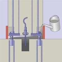
![Fig. 6 Erection in a gap [11].](https://www.bft-international.com/imgs/103946002_2804570526.jpg)
![Fig. 7 Tensile force perpendicular to the joint [11].](https://www.bft-international.com/imgs/103945985_ee4199dc34.jpg)
![Fig. 8 Shear force parallel to the joint [11].](https://www.bft-international.com/imgs/103946039_9a3a885305.jpg)
![Fig. 8 Shear force parallel to the joint [11].](https://www.bft-international.com/imgs/103946044_9be12cf91f.jpg)
![Fig. 9 Shear force perpendicular to the joint [11].](https://www.bft-international.com/imgs/103946067_21a4ac5ffb.jpg)
![Fig. 9 Shear force perpendicular to the joint [11].](https://www.bft-international.com/imgs/103946036_66650c9a57.jpg)
![Fig. 9 Shear force perpendicular to the joint [11].](https://www.bft-international.com/imgs/103946030_a887caf557.jpg)
![Abb. 11a Möglichkeiten der Querkraftübertragung bei Stützenschuhsystemen [11]: über Reibung.](https://www.bft-international.com/imgs/103946031_668919bce0.jpg)
![Abb. 11b Möglichkeiten der Querkraftübertragung bei Stützenschuhsystemen: über zusätzlichen Anker [11].](https://www.bft-international.com/imgs/103946053_aa130ddaaa.jpg)

Twist-on connectors and rebend connections in protective boxes are user-friendly system solutions for connecting reinforcement between different construction and concrete sections. Approved flexible steel cable loops and column shoes are suitable means for connecting precast concrete walls and columns. While in the past the formwork in transition areas of the reinforcement was frequently cut, reinforcement connections are easier and quicker to use, even on modern formwork elements.
Twist-on connections are conventional ribbed reinforcement steels with threaded ends that are screwed into the coupling bars of the first pouring section at the site. The use of screwed-on connection bars obviates the need for double reinforcement layers at joints, which is of special advantage in highly-reinforced members, e.g. columns, and eliminates extreme reinforcement concentrations. High-quality approved twist-on connectors ensure a secure mechanical connection, both for static and non-static loadings. Backbending reinforcement in protective boxes are delivered as complete systems and are simply fixed to the formwork of the first pouring section. After the formwork has been removed, the reinforcing bars are bent up (rebent). Rebend reinforcement requires no technical approval by the building authorities. DIN 1045-1 [1] refers to the DBV code of practice on the backbending of reinforcing steel and requirements on protective boxes „Rückbiegen von Betonstahl und Anforderungen an Verwahrkästen“ [2], which regulate the conditions for application.
In precast plants, flexible cable loops in individual boxes or as rail profiles are nailed to the formwork of the precast members. At the construction site, only the cable loops located on the oppositely placed precast members need to be folded out and a longitudinal bar installed to prevent splitting in lap areas. Subsequently, the joint is grouted with high-strength concrete. The design resistances for loadbearing connections are regulated by the regulatory authorities so that several precast walls can be joined to form one shear wall.
Precast reinforced-concrete columns can today be installed much more economically. A range of modern and installation-friendly erection systems for the connection to foundations or flexurally stiff column-beams connections is available.
Whether twist-on connections, backbending reinforcement, flexible cable loops or column shoes: modern system connections can do without projecting bars at transitions between structural members. This reduces the risk of injury at the construction site or at the completed structure. They provide contractors with a high measure of flexibility in planning the construction sequence und guarantees on-time completion of the building works under construction. The use of these products, moreover, greatly facilitates the planning and execution of a project. The factory-profiled protective boxes guarantee the specified roughnesses and meet high quality criteria.
The following article examines significant aspects of the use of such system solutions.
Special regulations for rebend connections
To simplify setting up the formwork on the demarcation line of the concrete sections, intersected by reinforcing bars, thinner reinforcing bars (ds ≤ 14 mm) may be initially installed bent-up. Later, after the formwork has been removed, the bars are bent-back into their intended position for the connection. The DVB code of practice on back-bending and the requirements governing protective boxes contain detailed specifications, regulations and instructions for backbending [2].
Prefabricated reinforcement connections
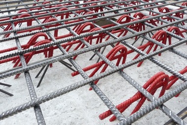
The bent-up reinforcing bars are gathered together in so-called protective boxes to facilitate the reinforcement work and are offered under various product names as prefabricated reinforcement connections (Fig. 1).
Prefabricated reinforcement connections are in this context defined as prefabricated elements for manufacturing lapped splices of the reinforcement at the boundaries of concrete sections and where the connecting bars are initially bent in a protective box in a position that prevents them from penetrating the formwork on the first concrete section. Following formwork removal, the connecting bars are bent back into their original position. They can also be used as reinforcement without overlap for short corbels or similar elements.
Requirements
Prefabricated reinforcement connections are available on the market in a wide range of designs. They differ from each other essentially through the arrangement and the form of the reinforcing bars as well as the profiling of the protective box. The classification into roughness categories depends on the profiling of the protective (see Fig. 2 and Table 1) in accordance with DIN 1045‑1, which has to be demonstrated through checks and in tests. Special requirements are made on the geometry and the stiffness of the protective boxes to ensure secure installation and reliable functioning in the structure. The manufacturer’s data sheet must therefore contain at least the following information:
» reinforcing steel type
» bar diameter, bar spacing
» dimensions of bar forms, effective connection lengths
» dimensions and materials used for the protective boxes
» position of bar penetrations
» documented evidence of box profiling
» corrosion protection, where required.
Design
Reinforcement connections must be entered in the construction drawings, stating make and type. For an alternative achieved with equivalent reinforcement connections, the following minimum data must be provided:
» the width of the protective boxes
» bar diameter and spacing
» the materials quality
» surface characteristics.
Accordingly, the commonly used information “company X, type Y or equivalent” is not sufficient. Changes of that kind are anyhow permissible only with the approval of the structural engineer. The determination of the areas used for the design for bending and shear force in the area of the boxes is done in accordance with as specified in the DVB code of practice [2]. In cases a and b, the rear-suspended reinforcement is effective as bond reinforcement in the joint, the shear force is transmitted in parallel to the joint. Cases c and d consider hinged line supports. The rear-suspended reinforcement functions as longitudinal reinforcement of the connected structural member, where the lower layer of the flexural reinforcement overlaps the slab and the upper layer is required only as nominal reinforcement. If the upper layer is calculated as loadbearing, a fixed connection in accordance with c has to be verified. This involves in general stair landings and corbels.
Execution
The boxes must be fixed in place in their exact position as specified in the construction drawings. Special attention has to be placed on adherence to the concrete cover. If the reinforcement in the boxes is not correctly aligned and immovably fixed in the specified position, it must be connected to the connecting reinforcement of the respective concrete section and in this way restrained in the correct position. Protective boxes are allowed to remain in a structure only when the stiffness of the materials of which the box is made corresponds at least to the stiffness of the concrete. Boxes made of plastics must therefore be completely removed. Boxes that have become detached from the concrete and/or boxes whose hollow sides lie on the concrete must likewise be removed or permanently connected to the concrete surface by means of follow-up injection. Fig. 4 illustrates the general installation process.
Particularities of flexible reinforcement
connections
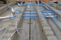
Connections between concrete elements can be realized not only with the typical reinforcing bars, but also with looped elements. Fig. 5 shows systems that are commonly available on the market.
The advantage of these flexible reinforcement connections is that they can also be used for precast members that are installed in gaps (Fig. 6):
» tensile forces perpendicular to the joint
» shear forces in parallel to the joint
» shear forces perpendicular to the joint.
Where tensile forces act perpendicular to the joint, crack widths of 0.4 mm result in the joint from cable loops already in the presence of relatively low cable forces. For this reason, the general technical approvals granted earlier do not extend to tensile forces perpendicular joints. For the inner tensile forces induced by the shear forces, additional structural measures (e.g. ring anchors) had to be provided.
A short while ago, the transmission of tensile forces perpendicular to joints was included in the approval [11]. Here, designed tensile actions can now transmitted via the system. Ring anchors or similar devices are moreover no longer required. Details are shown in [11].
Shear forces parallel to joints can, for example, result from the longitudinal stiffening of a building against wind loads. Fig. 8 shows a model for transmitting these shear forces across a joint. The shear force arising in the joint is here divided up into a tension strut and a compression strut. The magnitude of the compressive and/or tensile force depends on angle a. As can be seen in the model presented in Fig. 8, there develops between the precast members opposite the protective cases an inclined compression strut. The tensile force is transmitted to the overlapping cable loops.
In special cases, shear forces can also arise perpendicular to a joint. This can, for example, result from structural members loaded by earth or wind pressure. The geometry of a joint is of special significance for the transmission of shear forces perpendicular to a joint (Fig. 9). It can be assumed that a compression strut like the one shown in Figure 9 can develop between the concrete interfaces of the opposite precast members. The tensile force is transmitted to the overlapping cable loops.
In situations where shear forces act simultaneously parallel and perpendicular to the joint (Fig. 10), the interaction diagrams relevant to the system used have to be taken into consideration.
The technical approval relates to members subjected primarily to static loading. If the occurrence of restraint actions due to temperature changes or free weathering cannot be precluded, an analysis on the restriction of the crack width has to be performed. The analysis must show that the crack width at the precast reinforced-concrete connection that occurs due to the loading will be restricted to wk ≤ 0,3 mm. No additional crack widths will result from shear loading. For shear loading perpendicular to a joint, a tensile component with at least 1.5 times the shear force to be transmitted perpendicular to the joint has to be taken into account for taking up the expanding forces as defined in DAfStb Heft 525 [12].
Erection of the precast parts
The wall members are placed in a mortar bed or on shims in the aimed for connection and adjusted in height. The joints of members usually have a width of 20 mm with a tolerance of -10 mm/+20 mm. In vertical direction, the opposite loops should touch and/or be spaced no more than 20 mm apart. After the loops are aligned, a reinforcing bar ø 12 mm is pushed through the loops from above and the sides of the joints shuttered. The base surface has to be carefully cleaned. Loose parts and parts that interfere with the bond as well as cement slurries, formwork oil and similar pollutants must be removed by appropriate means. The joints are continuously filled with high-strength, low-shrinkage concrete grout. Filling heights of up to 3.5 m are possible.
The weakest point of a joint connection is always the joint sealing. The joint connections can transmit the acting forces fully only in joints that have been flawlessly and completely filled.
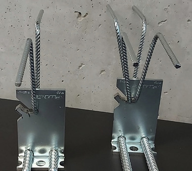
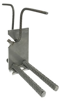
Support shoe systems
Support shoe systems consist in part of the anchorage of the foundation (“foundation anchorage”) and a further element that is integrated in the precast column (“support shoe”). The connection is established via the threaded end of the foundation or connection anchors, through-holes in the support shoes as well as nuts. After the columns have been erected, the joint must be injected with suitable mortars.
Support shoe systems offer considerable advantages to all parties involved in the design, manufacture and erection of a structure (compare Table 2).
Design and dimensioning
The following analyses of the loadbearing capacity have in general to be performed in the design and dimensioning of support shoe systems (Table 3). In addition, the requirements on corrosion and fire protection have to be observed.
Special attention has to be paid to the design of the end anchorage in the foundation. The design of straight and bent-up bar ends of anchorages and/or lapped splices takes place in accordance with DIN 1045‑1 or EC 2. The responsible engineer and/or the design engineer himself has to perform a check of the transmission of forces and/or the back anchorage of the forces in the adjacent member based on valid standards and/or regulations and the state of the art. This task is not part of the approval and/or the installation instructions of the manufacturers of system products of this kind. Resisting tensile shear stresses in anchorage or lapped areas must be taken up through appropriate additional reinforcement as specified in the applicable standards.
Where shear forces have to be transmitted, additional checks and/or structural measures must be carried out (see Fig. 11).
The use of system solutions offers considerable advantage in design, planning and the flow of the construction process. The use of the modern construction methods described here bring considerable advantages in terms of speed, safety and quality.